![]()
I2C Multiplexers


What is a multiplexer?
In simple terms in the context of I2C communication, a multiplexer allows for one I2C bus to appear to be 4 or 8 or more separate buses. In the simple case of a single multiplexer on an I2C bus, it allows the processor on the motherboard to switch between the 4 or 8 channels and see only devices on each channel at once. This multiplies the number of I2C devices that can be connected to a command station.
This enables:
Using multiple devices with the same, hard coded I2C address (including displays)
Being able to use more devices than normal due to limited address ranges
Split an I2C bus electrically to overcome capacitance/resistance issues which can dramatically improve reliability
At present up to 8 multiplexers can be supported on a single command station, resulting in up to 64 distinct I2C buses and hundreds of devices. In practise you will be limited by the amount of RAM available on your command station.
Which multiplexers are supported?
Both TCA9548A/PCA9548A 8-channel, and TCA9544A/PCA9544A 4-channel multiplexers have been tested and are supported at the moment. Equivalent and compatible multiplexers should work, but we have not completed testing of the others at this time.
Multiplexer I2C Base Addresses
Most multiplexers allow you to set them to the I2C address range of 0x70-0x77. The issue with 0x70 is that it is also a broadcast address used by PCA9685 Servo Modules, and therefore any attempt to use this address can create issues. We therefore suggest you set all of your multiplexers into the range 0x71-77.
Note
EX‑CommandStation will only scan for multiplexers in the address range 0x71-77, so please set your multiplexers into this address range.
Locating devices on I2C buses and multiplexer sub buses
It is important to note that an I2C multiplexer operates more like a switch than a true multiplexer, meaning that when a specific sub bus is selected, that sub bus is connected to the main bus the multiplexer is connected to.
This results in any device on that sub bus being connected to the main I2C bus, meaning a device on a sub bus will conflict with another device on the main bus at the same address.
What does this mean?
Simply, it means ensuring that when you are using multiple devices with the same address (eg. multiple OLEDs on 0x3C), do not connect any of those devices to the main I2C bus, and instead ensure they all exist on a sub bus of the multiplexer only.
How do I use a multiplexer?
Shown below is an Arduino Mega with a TCA9548A 8-channel multiplexer attached.
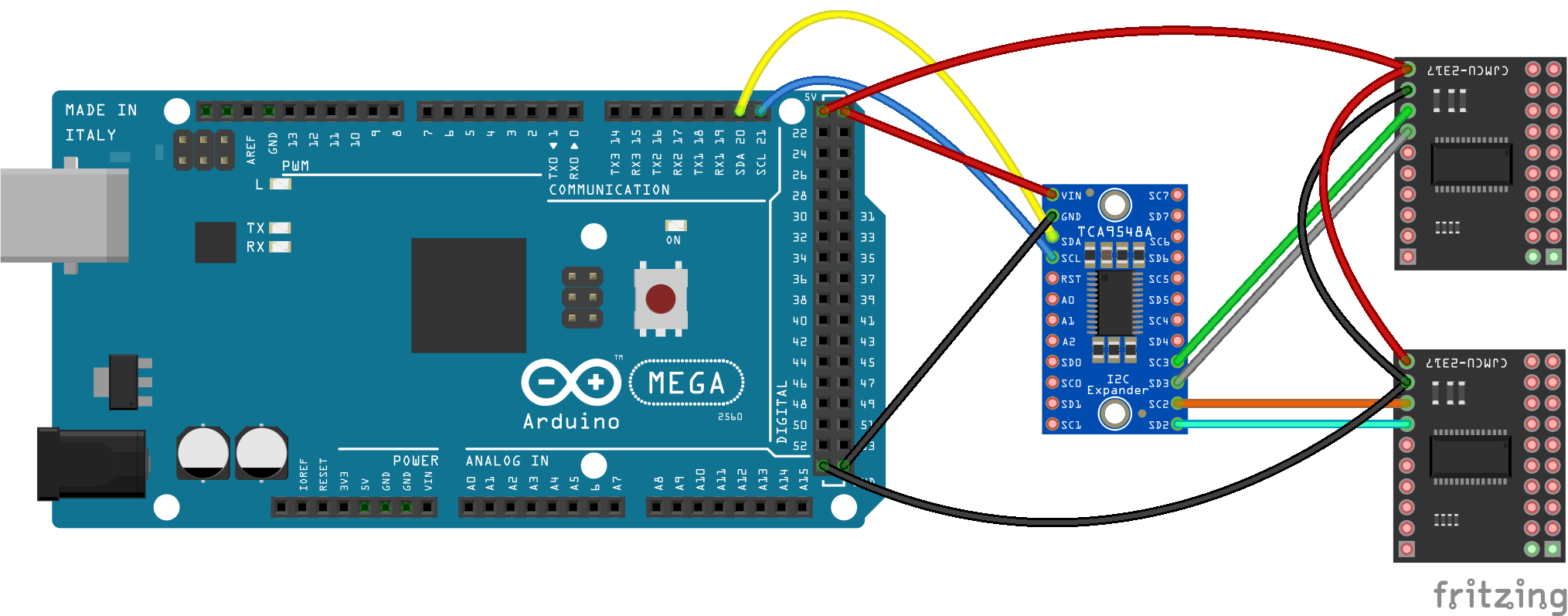
As you can see, we have two identically addressed I2C peripherals attached to independent channels SC2 and SC3 so that they don’t clash. The EX‑CommandStation software is able to distinguish between the two with new extended addressing formats. As a helpful aid, the command station will discover the multiplexer and then probe each channel to see what, if any, I2C devices are attached.
<* License GPLv3 fsf.org (c) dcc-ex.com *>
<* I2C Device found at 0x3D, OLED Display? *>
<* I2C Device found at 0x71, I2C Mux? *>
<* I2C Device found at {I2CMux_0,SubBus_0,0x3C}, OLED Display? *>
<* I2C Device found at {I2CMux_0,SubBus_0,0x60}, ?? *>
<* I2C Device found at {I2CMux_0,SubBus_1,0x40}, PWM? *>
<* I2C Device found at {I2CMux_0,SubBus_1,0x41}, PWM? *>
<* I2C Device found at {I2CMux_0,SubBus_3,0x20}, GPIO Expander? *>
<* I2C Device found at {I2CMux_0,SubBus_4,0x3C}, OLED Display? *>
<* I2C Device found at {I2CMux_0,SubBus_5,0x3C}, OLED Display? *>
<* 128x64 OLED display configured on I2C:0x3d *>
<* LCD0:DCC-EX v4.2.34 *>
<* LCD1:Lic GPLv3 *>
In this example, we see OLED display 0 is attached directly to the main I2C bus on address 0x3D, and that an 8-channel multiplexer (Mux) is also seen at address 0x71. Hanging off this multiplexer we have a variety of devices off SubBus_0, SubBus_1, SubBus_3, SubBus_4 and SubBus_5. You will notice that on SubBus_4 and SubBus_5 we have two identical OLED displays both using address 0x3C. But because they are isolated from one another by the multiplexer, the command station is able to write to them entirely independently.
In order to declare these OLED displays, we need a way to tell the code where to find them. So for the example above, we need to add lines to “myAutomation.h” making use of the HAL() macro:
// Create a 128x32 OLED display device as display number 1
// (line 0 is written by EXRAIL 'SCREEN(1, 0, "text")').

HAL(HALDisplay<OLED>, 1, {SubBus_4, 0x3c}, 128, 64)

// Create a 128x32 OLED display device as display number 2
// (line 0 is written by EXRAIL 'SCREEN(2, 0, "text")').

HAL(HALDisplay<OLED>, 2, {SubBus_5, 0x3c}, 128, 64)
As you can see from the comments in this code, both of these displays can now be written to from EXRAIL using the SCREEN() directive. See the EXRAIL command reference for notes on using it.
Note that when there are multiple multiplexers on the I2C bus, we will need to also specify which mulitplexor the display is connected to. So that declaration looks like this in “myAutomation.h”:
// Create a 128x32 OLED display device as display number 1
// (line 0 is written by EXRAIL 'SCREEN(1, 0, "text")').

HAL(HALDisplay<OLED>, 1, {I2CMux_0, SubBus_4, 0x3c}, 128, 64)

// Create a 128x32 OLED display device as display number 2
// (line 0 is written by EXRAIL 'SCREEN(2, 0, "text")').

HAL(HALDisplay<OLED>, 2, {I2CMux_0, SubBus_5, 0x3c}, 128, 64)
As you can see, things can get quite complex, but this also means it is very flexible.
To configure the PWM and GPIO modules hanging off the mulitplexor on the other sub-buses, you would need something like the following in “myAutomation.h”:
//=======================================================================
// The following directive defines a PCA9685 PWM Servo driver module.
//=======================================================================
// The parameters are:
//   First Vpin
//   Number of VPINs
//   I2C address of module

HAL(PCA9685, 100, 16, {I2CMux_0, SubBus_01, 0x40})
HAL(PCA9685, 116, 16, {I2CMux_0, SubBus_01, 0x41})

//==============================================================================
// The following directive defines an MCP23017 16-port I2C GPIO Extender module.
//==============================================================================
// The parameters are:
//   First Vpin
//   Number of VPINs
//   I2C address of module
//   Vpin for interrupt (optional)

HAL(MCP23017, 196, 16, {I2CMux_0, SubBus_03, 0x20})
Note
Note that any currently supported I2C device can be connected to any port of any multiplexer, provided they are declared in “myAutomation.h” with the HAL() macro, with the correct addressing for multiplexer and sub-bus. It is probably easiest to connect all the I2C devices to your multiplexers and let EX‑CommandStation probe for the them and any devices off each sub-bus, so you can use the console output to guide you in creating the HAL() macro declarations for “myAutomation.h”.