EX-Toolbox User Guide
Various screens can be accessed via the dropdown menu or by swiping left and right.
CV Programming
DCC Decoder CV programming is available:
- on the Programming track (PROG) - Service Mode.
- on the main line (MAIN) - Operation mode / Ops Mode.
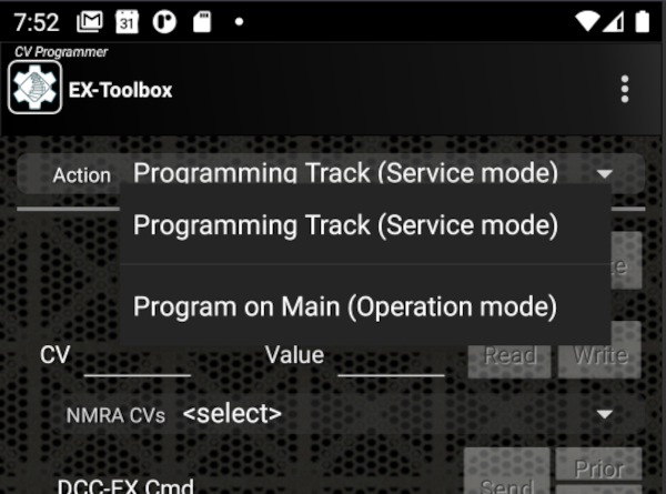
By default EX‑Toolbox shows the Service Mode options. To switch to Operation Mode, select "Program on Main (Operation Mode)" on the drop down list at the top of the screen.
CV Programming (Service Mode)
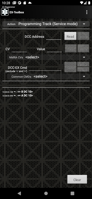
Service Mode CV Programming is available form the 'CV Programming' screen, when 'Programming Track (ServiceMode)' is selected in the drop down list at the top of the screen.
Service Mode CV Programming allows you to both Read (if the decoder/loco supports it) and Write CVs.
You do not need to know the DCC Address of the decoder being changed, as all decoders/locos currently on the programming track will have the CV changed at the same time.
Track power is managed automatically by the Command Station.
Do not be temped to manipulate decoder addresses by reading or writing individual CVs, this is very complicated and may require as many as 6 Cvs to be understood.
On this screen you can:
-
read the decoder's DCC Address. (this reads multiple CVs to obtain the driveable address, which may be a consist)
Click the Read button on the DCC Address row. -
write a new DCC Address to the decoder. (This writes multiple CVs to automatically manage long and short addresses.)
Enter the address and click the Write button on the DCC Address row. -
read a CV value from the decoder
Enter the CV number and click the Read button on the CV row. -
write a CV value to the decoder
Enter the CV number, enter the value and click the Write button on the CV row. -
select from a list of named, common CVs
If you select a 'common CV value' it will enter the CV number into the field. From there follow the instructions above for reading or writing the CV. -
issue <> commands to the EX‑CommandStation
CV Programming (Operation Mode)
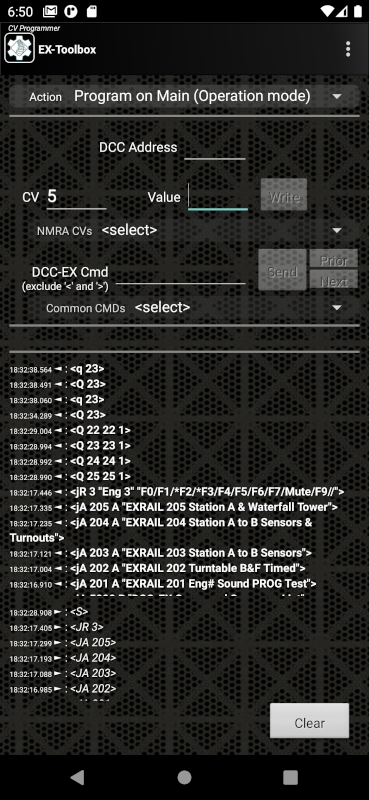
Operation Mode CV Programming is available from the 'CV Programming' screen, when 'Program on Main (Operation Mode)' is selected in the drop down list at the top of the screen.
Operation Mode CV Programming ONLY allows you to Write CVs.
To use Operation Mode CV Programming you must know the DCC Address of the decoder/loco you want to change. Note: you should never try to change the DCC Address of the decoder/loco using Operation Mode CV Programming.
On this screen you can:
-
write a CV value to the decoder
Enter the DCC Address of the decoder, enter the CV number, enter the value and click the Write button on the CV row. -
select from a list of named, common CVs
If you select a 'common CV value' it will enter the CV number into the field. From there follow the instructions above for writing the CV. -
issue <> commands to the EX‑CommandStation
Issuing <> Commands
On several of the screens in EX‑Toolbox you can issue native DCC-EX <> commands to your EX‑CommandStation.
Enter the command you want to send, and click Send.
The command you send, and any responses from the command station will be shown below.
If you select a 'common command value' it will enter the command the field. From there follow the instructions above for issuing the command.
You can use the Next and Prior buttons to retrieve previously issued commands.
Speed Matching
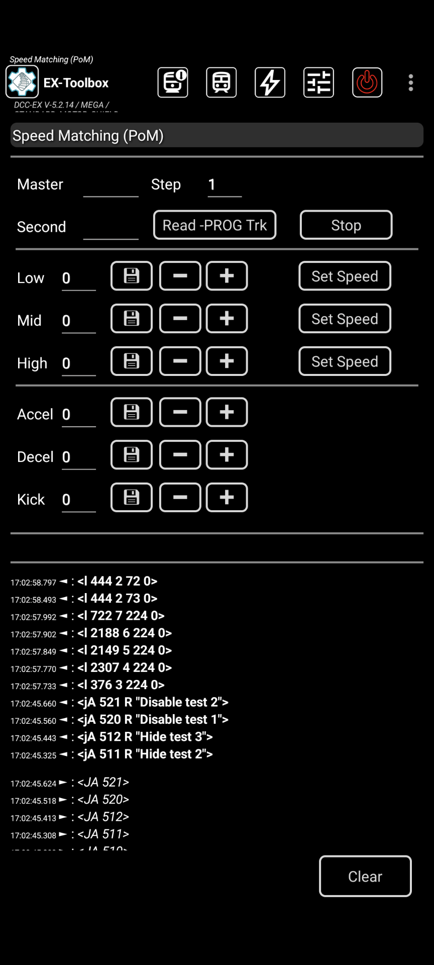
Speed Matching assists with making two or more locos run at similar speeds.
Requirements
-
A loop of track.
-
A loco that you wish to be the Master. i.e. that you want to make the other locos match.
-
One or more 'Second' locos that you wish to match to the Master.
-
All the locos have been run for 5-10 minutes to warm them up. Many locos run differently when warm.
Assumptions
-
You have already configured the 'Master' to be the way you want it and the other locos to behave.
-
The 'Master' should be the naturally slowest loco of the set, not necessarily the one that will be run in the lead position.
i.e. Test your locos on their default settings first, and find the slowest. -
The low speed test uses a speed setting of 5 (0-126). If your locos don't start moving at that setting it would be advisable to adjust Low speed setting and/or the Kick Start of the 'Master' first.
-
At least, the 'Second' loco is configured to use the High, Mid, Low CVs, not the full 28 step 'Speed Table'. (Part of CV29) Not critical, but it is advisable to have the 'Master' also use the High, Mid, Low CVs.
-
The 'CV Programming' Page of EX‑Toolbox has a feature specific to CV29. When you read CV29, it explains what you need to change the value to to disable the 'Speed Table'.
-
It is highly advisable that BACK-EMF is turned off on all locos that will be run in a consist. If you don't you will likely encounter surging of the locos as they speed up and slow down under individual load.
BACK-EMF is referred to by some manufacturers as 'Dynamic Compensation for Speed Stabilisation', 'Scaleable Speed Stabilisation' or 'Load Compensation'. Unfortunately there is no standard way to disable BACK-EMF. You will need to refer to the manuals for your decoders.
This page has a detailed explanation of BACK-EMF and details on how to change it for a number of manufacturers.
It is well worth viewing the video before starting as it makes the process clear in a way text does not.
Instructions
-
Put the/a second (non-master) loco on the PROG track. (see Notes)
-
Click
Read -PROG trk.
This reads 8 CV values, including the loco address and CV29, and loads them in to the fields, with a 3 second delay between each read.
Watch for any -1 responses (failed reads), and redo the read if any have failed. -
Put the 'Master' on the MAIN track (the loop of track), along with the 'Second' loco.
-
Enter the DCC address of the Master.
-
Click the
Low Set Speedbutton.
Watch and adjust the speeds of the Second loco in relation the Master, util they run at the same speed.
Use the speed input or use the+and-buttons to adjust the second loco speed. -
Repeat for the 'Mid' Speed.
-
Repeat for the 'High' Speed.
Adjust the decoder momentum (Acceleration/Deceleration) and Kick Start as needed. Test by starting and stopping the locos from the three different speeds.
If you have more locos to match, repeat from step 2.
Notes:
-
By default, the
+and-buttons change the CV values by 1. You can change this step amount by editing the 'Step' field.
e.g. When I start on a loco, I normally have the Step at 10. When it gets closer to a match I change the step to 1. -
You don't need a separate PROG track. You can use the 'Track Manager' screen to temporarily set the loop of track to PROG for steps 2-3, then change it back to MAIN for steps 4 on.
-
Some decoders don't support Kick Start.
-
Some decoders don't allow you to turn BACK-EMF off. Check your decoder manual.
-
The low speed test uses a speed setting of 5 (0-126). If your locos don't start moving at that setting it would be advisable to adjust Low speed setting and/or the Kick Start of the 'Master' first.
Speedometer
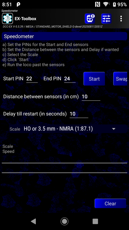
The Speedometer allows you to calulate the scale speed of a loco as it passes two defined sensors. The sensors can be of any type, but must be configured in your EX‑CommandStation and be a known (any) distance apart.
- Define you sensors in the EX‑CommandStation configuration, and note their numbers.
You will need to make them monitored for updates by adding JMRI_SENSOR commands in myAutomation.h, or by using the command input screen to enter<S vpin vpin 1>commands for each sensor. e.g.
JMRI_SENSOR(160,2)  // pins 160 and 161
or
JMRI_SENSOR(160) JMR_SENSOR(161)
or Enter commands:
<S 160 160 1>
<S 161 161 1>
When you run with either of these methods, the sensors will emit <Q 160> or <q 160> messags which the Toolbox will recognize.
Speedometer Instructions
-
Measure the distance between the sensors.
-
Enter the two sensor numbers on the speedometer screen.
-
Enter the distance between the sensors, and select the Scale.
-
Put the loco you want to measure on the track before the first sensor.
-
Start the loco moving.
-
The Speedometer will display the speed as the loco after it passes the second sensor.
The speed and times will automatically reset after 10 seconds, but you can overide this by clicking the Start button. Or you can change the delay period.
To check the speed in the opposite direction, simply reverse the sensor numbers, using the Swap button.
The Speedometer will remember the last used sensors and distance between sessions.
Loco Status
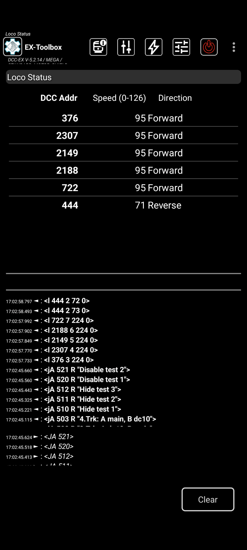
Loco Status allows you to watch changes to all locos being controlled by the command station.
Track Manager
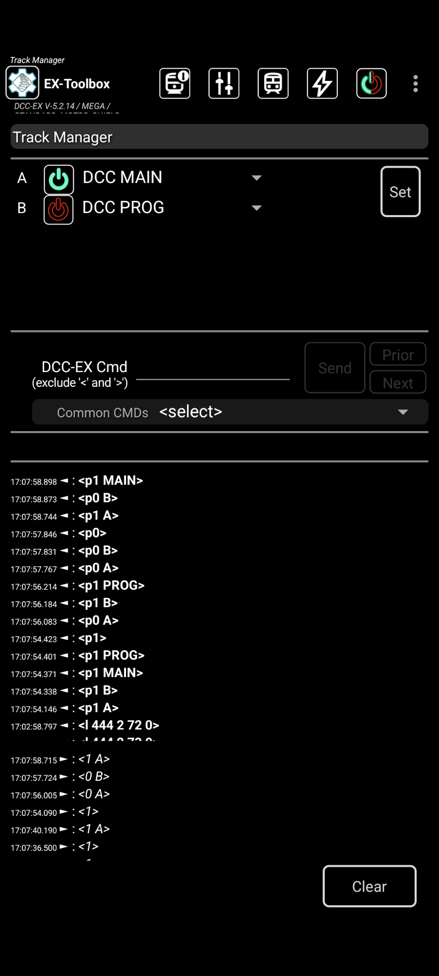
Track Manager allow you to change up to 8 channels (depending on the Motor Driver you are using)
Each channel can be one of:
DCC PROG- Programming TrackDCC MAIN- Main TrackDCC AUTO- Main track with auto reverseDCDC reversed polarity (DCX)OFF
Select the value you want for the channels and click Set.
Notes:
-
If you select
DCorDCXyou must select a DCC address for the channel before pressing Set. What ever address you select, selecting that address on your throttle (e.g. Engine Driver) will result in the DC locomotive on the track connected to that channel to respond. -
Only one channel can be
PROG. If you select more that one, one will turned OFF.
Servo motor testing and adjustment
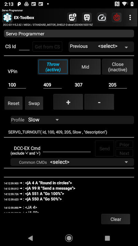
The 'Servo Motor Test' screen will allow you to test and fine tune the settings needed for configuring servo motors attached to the EX‑CommandStation. This is intended to be temporary. To permanently configure a servo motor you will need to record the values and include the in the configuration of your EX‑CommandStation.
-
Make sure your servo is NOT physically connected to anything that could be damaged if you move the serve too far.
-
Enter the VPin of the servo motor you want adjustment.
-
Enter any known starting values for Close, Mid, Throw.
-
Test the 'Close', 'Mid', 'Throw' positions by pressing the appropriate button. The servo will move to that position.
-
Fine adjust any of the three positions by using the + or - buttons.
The servo will gradually move. -
when you are happy, record the three values
EX‑Toolbox remembers the servos that you have changed (up to 10) in this and previous sessions, and you can select one of the previous servos from the drop down list. EX‑Toolbox will restore the last settings you used for the selected servo to the main fields.
Sensor testing
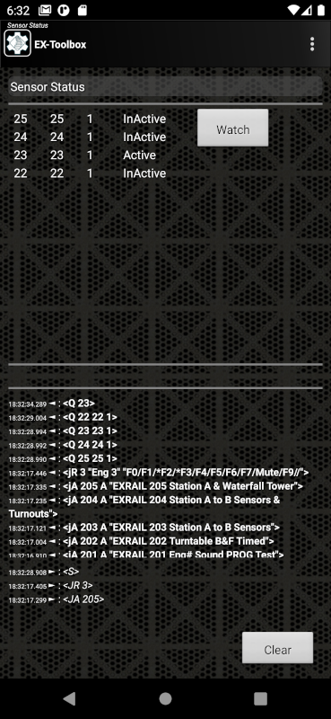
The 'Sensor Test' screen will allow you to test any sensors configured in your EX‑CommandStation, but only if they have been (temporarily) defined using JMRI_SENSOR in EXRAIL, or the <S vpin vpin 1> command.
When the screen opens the first 100 sensors found will be shown. Activity on the sensors will be shown on the screen. Scroll down to if needed.
The Watch button is generally not needed, but will force EX‑Toolbox to check the available sensors on the EX‑CommandStation again.
Current Meter
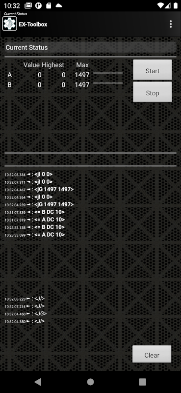
The 'Current Status' screen will show you the current values for up to eight channels on the motor driver on your EX‑CommandStation.
For each channel the following is shown:
- the up-to-date value in Milliamps.
- the highest value seen recently in Milliamps.
- the maximum value able to be supplied by the moto shield in Milliamps.
The readings start as soon as you open the screen and are paused as soon as you exit the screen. The readings are taken every three seconds.
You can manually stop the readings with the Stop button.
You can manually restart the readings with the Start button. This will also clear the 'Highest' values.
Roster

The 'Roster' screen will show you the current roster on your EX‑CommandStation.
Clicking on any individual loco in the roster will show you the details of that roster entry (the Loco's functions).

Neopixel Setup
![]()
The 'Neopixel' screen will allow you to experiment with any neopixels configured on your EX‑CommandStation.
Enter:
- the
Vpinof the Neopixel device. - the
count- The number of neopixels connected.
You can then adjust the colours (RGB values) of the neopixels with the sliders
Power
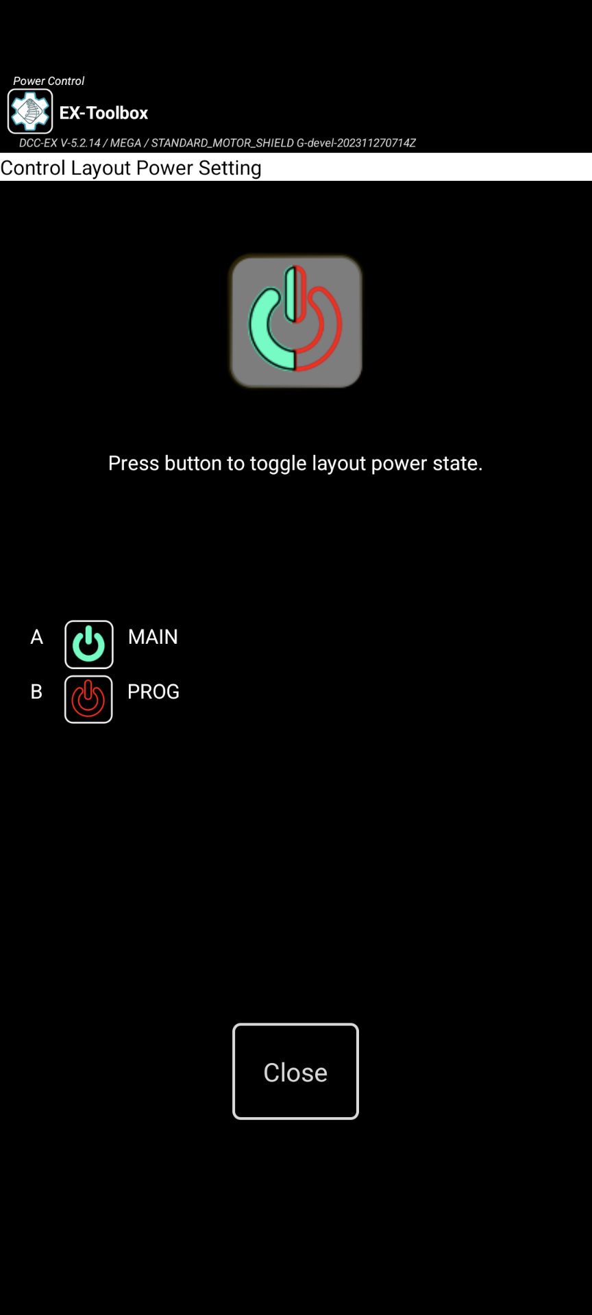
There are two ways to turn the Track Power on/off:
- Power Screen - accessed from the menu.
- Power Action Bar button - needs to be enabled in the preferences.
The Power Screen can be accessed from the Menu ‣ Power. This will open the Power Screen where there is a simple button that to turn the power on or off. Use the Close button or Android's Back button to return to the CV-Programming Screen.
If the Power Action Bar button is enabled, simply click on it to turn track power on or off.
Note, you can also optionally enable the Power Button on the Action bar in the preferences.
Preferences
Most configuration options are found in the Preferences which is accessed via the overflow menu which is normally three dots (⁞) or three bars (≡).
View log
Accessed from any of the main screens via Menu ‣ View Log.
This screen allows you to view the internal EX-Toolbox log of events. (referend to as 'logcat').
The option to Start recording to file creates a user-accessible file that can be sent to the EX‑Toolbox app developers to assist you in resolving a problem.
The file will be located on your Android device/phone at: Internal storage /Android/data/dcc_ex.ex_toolbox/files and will be named something like: logcat9999999999999.txt
Optionally enable the preference to include the timestamp on each line of the log.
Saving a Log File
To record a log file in EX‑Toolbox….
- Start EX‑Toolbox.
- From the menu, select
View Log. - Click Start recording to a file.
- Click
Close.
Attempt whatever is causing the problem a few times
-
Exit EX‑Toolbox.
-
Connect a USB cable to your device/phone and PC.
-
Allow access if the device/phone asks.
In some versions of Android you may also need to change the connection type on the device/phone from 'charging' to 'file transfer'. -
Open a file manager and find the connected device/phone.
-
Browse down to the folder …Internal shared
storage/Android/data/dcc_ex.ex_toolbox/files. -
Find the most recent file that looks like
logcatxxxxxxxxxxxxx.txt. e.g. logcat1699833098998.txt -
Attach that file to a message in discord using the
+button on the row of the message content.
About
This screen displays
-
Information about EX‑Toolbox.
-
Information about the EX‑CommandStation it is currently connected to (if any).
-
A page of basic information about EX‑Toolbox.