ESP32 + L298 Shields
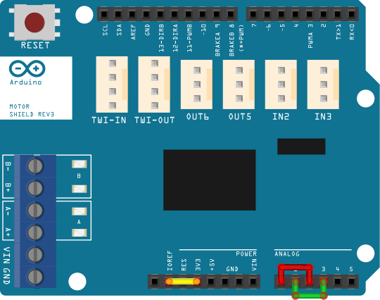
Genuine Arduino Motor Shield R3
-
IOREF voltage
- The IOREF pin on the ESP32 Uno form factor boards is 5V -- and not correct for a 3.3V microprocessor.
- To avoid damaging the ESP32’s analog inputs, correct the IOREF voltage by bending the IOREF pin on the L298 motor shield, and use a jumper to connect the 3.3V pin to IOREF on the motor shield itself.
- On the Genuino Arduino Motor Shield R3, the IOREF voltage is used as the supply voltage on the LMV358 op-amp and provides a spillway effect for the Schottky diodes on the A2, A3 pins of the motor shield.
-
Current sensing
- For current sensing bend or cut the A0 and A1 pins.
- On the top of the motor shield connect A0 to A2 and A1 to A3 via jumpers.
- On the Wemos D1 R32 ESP32, the A0, A1 pins are connected to GPIO2 and GPIO4 -- not useable for ADC input at the same time as WiFi. Connecting to the A2, A3 pins also provides the benefit of the Schottky diodes.
-
Motor define - STANDARD_MOTOR_SHIELD
- When STANDARD_MOTOR_SHIELD is defined in config.h, the definition for the WeMos D1 R32 is in place when ESP32 is selected as the build target.
Clone Motor Shields
-
IOREF voltage
- The IOREF pin on the ESP32 Uno form factor boards is 5V -- and not correct for a 3.3V microprocessor.
- Correct the IOREF voltage by bending the IOREF pin on the L298 motor shield, then IOREF will can be connected to the 3.3V pin to provide a spillway effect for the Schottky diodes on the A2, A3 pins of the motor shield.
-
Current sensing
-
Some clone shields have current sense circuits and can be used with Mega without modifications.
With ESP32-WROOM and Nucleo-F4, modifications are needed to protect ADC inputs. -
We have found no shields which have the same current sensing circuit as the Genuine Arduino R3.
Clone shields may have current sensing, but will not have the LMV358 op-amp, or the LMV358 op-amp supply voltage is connected to 5V instead of the IOREF pin.
-
-
Modifications to protect ADC inputs
- Connecting IOREF to 3V3 will enable the Schottky diodes which connect to the A2, A3 pins.
- Voltage divider resistor circuit is used to reduce the voltage from the op-amp

-
Motor define - STANDARD_MOTOR_SHIELD
- When STANDARD_MOTOR_SHIELD is defined in config.h, the definition for the WeMos D1 R32 is in place when ESP32 is selected as the build target.
- Review of motor shield define from MotorDrivers.h for ESP32 WeMos R1 D32
#define STANDARD_MOTOR_SHIELD F("STANDARD_MOTOR_SHIELD"), \
    new MotorDriver(25/* 3*/, 19/*12*/, UNUSED_PIN, 13/*9*/, 35/*A2*/, 0.70, 1500, UNUSED_PIN), \
    new MotorDriver(23/*11*/, 18/*13*/, UNUSED_PIN, 12/*8*/, 34/*A3*/, 0.70, 1500, UNUSED_PIN)

-
Motor define - ACEBOTT + L298 shield
- Even though the ACEBOTT A0, A1 pins locations are available, using the A2, A3 pins facilitates the voltage divider circuit along with the benefit of the Schottky diodes.
- A custom motor define will be needed in config.h
#define L298_ACEBOTT_ESP32 F("L298_ACEBOTT_ESP32"), \
    new MotorDriver(26/* 3*/, 16/*12*/, UNUSED_PIN, 19/*9*/, 34/*A2*/, 0.70, 1500, UNUSED_PIN), \
    new MotorDriver(17/*11*/,  5/*13*/, UNUSED_PIN, 23/*8*/, 35/*A3*/, 0.70, 1500, UNUSED_PIN)
#define MOTOR_SHIELD_TYPE L298_ACEBOTT_ESP32
