![]()
Adding WiFi


This page is specifically intended for a Conductor who intends to install just the recommended hardware. If you are a Tinkerer or Engineer or want to install some of the additional, or different, hardware from that recommended for a Conductor then we suggest that you look at the WiFi Connection page for the full list of WiFi options.
Warning
While the recommended Makerfabs ESP8266 WiFi Shield is now shipping with the correct firmware version and will work with EX‑CommandStation without modification, please be aware that the Espressif firmware shipped with Duinopeak ESP8266 WiFi Expansion and ESP-01 or ESP-01S devices will probably NOT work with EX‑CommandStation out of the box.
This can be corrected, but is probably beyond Conductor level and requires additional hardware.
See ESP8266 (WiFi Boards) - AT Version Issues and Solutions for details on how to check the version and how to correct it if needed.
The purpose of adding WiFi to your EX‑CommandStation is allow connection up to 5 WiFi throttles (e.g. phones) DIRECTLY to it, eliminating the need for a computer and another software controller.
However, WiFi is optional. If you wish to simply use your computer connected via a USB cable to the EX‑CommandStation using the JMRI application (or similar), you can skip ahead to the next page.
There are many ways to add WiFi to your Command Station. We will cover only one method here. You may need to know a little bit about networking, but if you can get your phone to connect to your home network, you can do this.
Note that you can click on any of the images to make them larger.
For a video to help you, click below.
Why Use WiFi?
BEFORE you purchase a WiFi card, please consider whether you actually need it.
If you wish to run trains from your phone, tablet or other wiThrottle Protocol devices connected directly to the EX‑CommandStation, without a PC involved, then you should follow the instructions below.
However, with the base EX‑CommandStation without a WiFi shield, you can use a USB cable to connect to a computer to run JMRI or our web browser based EX‑WebThrottle. So, if you intend to run trains from a PC, or by only using a web browser, JMRI, Rocrail, or similar, then YOU DO NOT NEED WiFi ON THE CS. If this the case you can skip ahead to the next page.
What you will need (for WiFi)
A EX‑CommandStation made from an Arduino Mega and a Motor Driver (from the previous page)
A WiFi board
Two (2) Male to Female Jumpers leads
Makerfabs ESP8266 WiFi Shield - installation instructions
Most boards based on the ESP8266 should work with the EX‑CommandStation. However, with all the variations and software versions out there this is the one that we recommend for people starting out with DCC-EX.
We like this board here at DCC-EX. It is simple, inexpensive, easy to use, and it works.

Figure 14 Makerfabs ESP8266 WiFi Shield
Installing the board follows the same procedure in the previous section on Initial Assembly. Start by noting the tab end of the board and align it with the tab end of the motor board. You will stack this board on top to make a three board stack.
Remove the plastic jumpers
Note the two black plastic jumpers: we need to remove both of them. You can pull them off with your fingers or needle nose pliers and either stick them in a drawer or move them to the side by having them connect via one side to any of the row of Rx pins. The other end of the connector will just hang out over the WiFi Board.
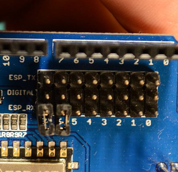
Figure 15 Remove the plastic jumpers
Align the boards
Turn the board so that the tab end is to the left and the power connectors on the other boards are to the right. You will be looking at the left side of the shield. Align it so that the pins align starting with the tab end of the boards. The Rx, Tx, 2, 3, 4, 5, 6, 7 pins on the Motor Shield line up with the 0 through 7 pins on the Makerfabs WiFi Board.
Start to get this row partially seated so all the pins are lined up with the holes. Note that there are more holes than pins. The two header holes closest to the power connectors will be empty.
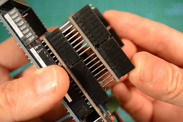
Figure 16 Get the left side pins aligned
Seat the boards
Now do the the other side. If all the pins are straight and lined up properly, hold both sides of the board and press it together gently (Figure 17).
Note that the pins are quite long and will not go all the way into the header. You should have even more of the pins showing between the bottom of the WiFi board and the top of the header on the Motor Board than between the Motor Board and the Arduino. This is normal (see Figure 18).
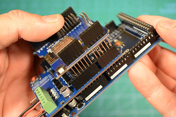
Figure 17 Get the right side pins aligned
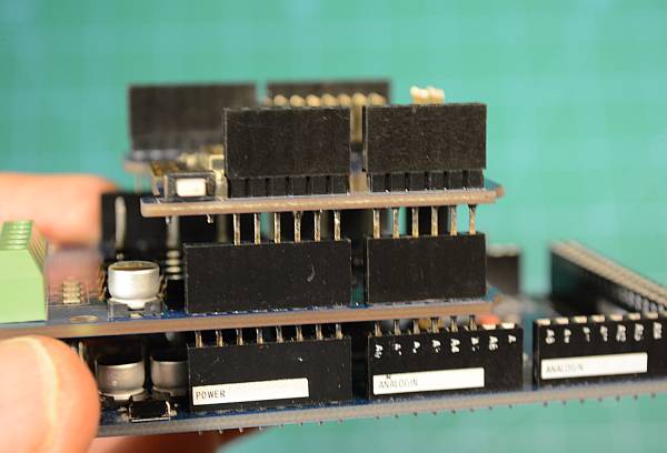
Figure 18 Fully seated boards
Install the jumper wires
We now need to connect The Transmit (Tx) and Receive (Rx) pins on the ESP8266 to the Rx and Tx pins for Serial1 on the Mega. The Mega has one serial port connected to the USB port, and then 3 extra ones we can access from pins on the board. You can think of Tx as “talking” and Rx as “listening”. That will help you remember that if one thing is talking, the other has to use its ears to listen. So we must connect the Tx of the WiFi board to Rx1 on the Mega and the Rx pin on the WiFi Board to Tx1 on the Mega.
There are three rows of pins on the Makerfabs WiFi shield. The middle pins each connect to one of the first 8 pins on the header. Pin 0 goes to header pin 0, pin 1 goes to header pin 1, and so on. We aren’t going to need those. With the plastic jumpers removed, nothing will be connected to any of those pins on the WiFi Board, and therefore not connected down to the Mega through the Motor Shield.
ALL of the pins in the row marked Tx (the row closest to the header) are connected to the Tx pin of the ESP8266. ALL of the pins in the row marked Rx (the row closest to the middle of the board) are connected to the Rx pin on the ESP8266.
Note
The screen printing on the board may make it hard to see which pins are 18 and 19, they may not be aligned exactly.
Count the pins if you need to to make sure that you are using the correct ones.
Take a jumper wire and connect it to any one of the Tx pins on the WiFi Board, and connect the other end to the Rx1 pin on the mega (pin 19).
Take a second jumper wire and connect it to any one of the Rx pins on the WiFi Board and connect the other end to Tx1 on the mega (pin 18).
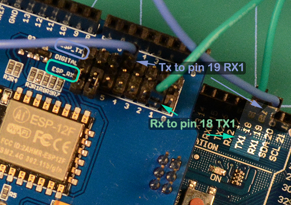
Figure 19 Install the jumper wires
Next Steps - Install the Software
Click here or click the “next” button to learn how to install the software on your EX‑CommandStation.