Keyestudio IOT ESP32 PLUS Development Board + EX8874
Keyestudio ESP32 Beta Testing
Please note that the Keyestudio ESP32 board is currently in Beta testing, so this information may change at any time. If using this board, we highly recommend joining our Discord server and request access to the #beta-testing channel.
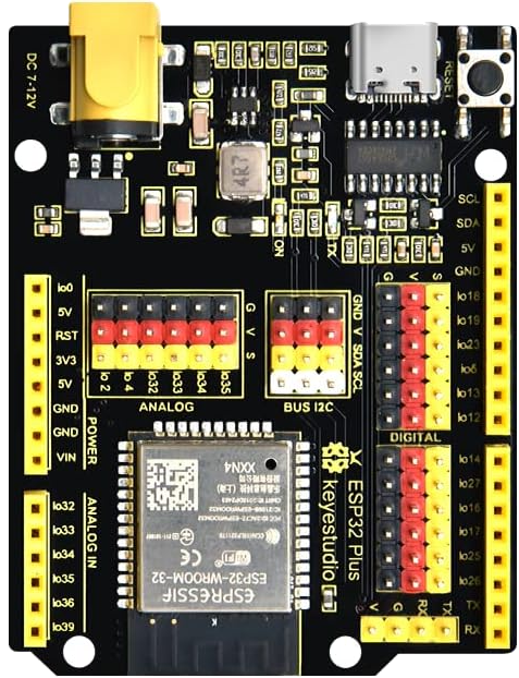
Keyestudio IOT ESP32 PLUS Development Board
- Please report any anomalies when using the pins in the suggested custom motor defines.
- A custom motor define is required when using the Keyestudio IOT ESP32 PLUS Development board, as the pins are in different locations VS the WeMos ESP32.
- Do not be fooled by the
Vpin on the I²C header block as it is 5V, and there is no onboard level shifting of the SDA SCL pins.
Keyestudio IOT ESP32 PLUS Development Board VS WeMos R1 D32
- Fewer modifications may be required.
- WiFi does not need the resistor.
- Pin locations A0, A1 can be used for current sensing.
- The default pins can be used on EX8874.
Incorrect IOREF voltage
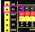
The pin in the IOREF location is 5V and labeled 5V on the board.
EX8874 requires IOREF voltage at 3.3V when used with ESP32 or other 3.3V microprocessors.
Warning: Without modification the ADC inputs and I2C pins will receive up to 5V when the IOREF pin is 5V which will damage the ESP32 board and likely destroy it. As such it is vital that the modifications below are made.
-
Option A: The prefered work-around to the incorrect 5V pin is to modify the EX8874, using the
3V3 IOREF Overridesolder pad on the EX8874. -
Option B: The
IOREFpin location is labeled5V. An acceptable workaround that does not require soldering is for the corresponding pin on the EX8874 to be bent out, and theIOREFto be jumpered to3V3header on the EX8874.
See the Incorrect IOREF voltage page for details on how to correct the IOREF voltage for this board combination.
One EX8874
Note:
- Keyestudio IOT ESP32 PLUS Development Board motor defines are not included in
MotorDrivers.h - Do not edit
MotorDrivers.h; a custom motor define should be added inconfig.h - Note how the ESP32 GPIO pin numbers are used, and the Arduino pin locations are shown/commented.
Add the following lines to your config.h and remove any existing #define MOTOR_SHIELD_TYPE ... line.
  #define EX8874_KEYES_ESP32 F("EX8874_KEYES_ESP32"), \
    new MotorDriver(25/* 3*/, 19/*12*/, UNUSED_PIN, 13/*9*/, 32/*A0*/, 1.52, 5000, 36 /*A4*/), \
    new MotorDriver(23/*11*/, 18/*13*/, UNUSED_PIN, 12/*8*/, 33/*A1*/, 1.52, 5000, 39 /*A5*/)
  #define MOTOR_SHIELD_TYPE EX8874_KEYES_ESP32
- When one EX8874 motor shield is used with Keyestudio IOT ESP32 PLUS Development Board, the default EX8874 pins are used.
output |
Current Sense |
PWM Enable |
DIR Signal |
Brake |
Fault |
Notes |
|---|---|---|---|---|---|---|
| A | 32 pA0 | 25 p3 | 19 p12 | 13 p9 | 36 pA4 | Default pins |
| B | 33 pA1 | 23 p11 | 18 p13 | 12 p8 | 39 pA5 |
Single EX8874 Checklist
- Cover the barrel connector on Keyestudio IOT ESP32 PLUS Development Board, as VIN power will be provided by EX8874
- IOREF Override set to 3v3
- IOREF pin is bent or trace is cut or both
- Add the custom motor define - 4 lines in
config.h
Stacked EX8874
- Reminder: No modifications are needed when stacking an EX8874 on an EX-CSB1 for 4 track outputs.
- IOREF: The IOREF override is also needed for the top shield. See the Incorrect IOREF voltage page for details.
-
VIN: Refer to instructions on cutting the VIN trace and disabling the regulator for the top EX8874. (See Option 1 below.)
-
Stacking (2) motor shields on Keystudio ESP32 requires additional modification of the second/top shield:
-
Disabling the VIN on the top EX8874
-
Option 1 - Cut the traces on the top EX8874
- Cut the regulator to VIN pin on the top of the PCB
- Cut the "Regulator Enable" trace on the bottom of the board
-
Option 2 - bend the VIN pin
- Bend the VIN pin of the top EX8874 out so that it does not make contact with the lower EX8874
-
-
Use of solder pad for 8 alternate pins (not the fault pins)
- For Fault pins, bend the A4 and A5 pins on the top motor shield, so that they do not contact the lower shield
-
^ Also for Fault pins,
io2will need to be jumpered toA4on the EX8874.io4will need to be jumpered toA5on the EX8874.
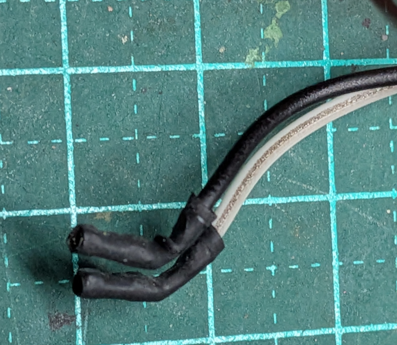
To do so, to avoid fouling with the EX8874, the pins on the ESP32 board labeledio2andio4will either;- need to be bent about 45 degrees so that jumpers can be put on them, or
- use modified jumper cables with the plastic ends removed, bent and covered with heat shrink.
-
See the Stacking two motor shields on the EX8874 page for details on how to alter the board for this combination.
First EX8874
output |
Current Sense |
PWM Enable |
DIR Signal |
Brake |
Fault |
Notes |
|---|---|---|---|---|---|---|
| A | 32 pA0 | 25 p3 | 19 p12 | 13 p9 | 36 pA4 | Default pins |
| B | 33 pA1 | 23 p11 | 18 p13 | 12 p8 | 39 pA5 |
Second EX8874
output |
Current Sense |
PWM Enable |
DIR Signal |
Brake |
Fault |
Notes |
|---|---|---|---|---|---|---|
| C | 34 pA2 | 26 p2 | 5 p10 | 14 p7 | 2 pA4 | use alternates for 8 pins |
| D | 35 pA3 | 16 p5 | 17 p4 | 27 p6 | 4 pA5 | Bend & jumper. See notes |
- A custom motor define will be needed in
config.h
  #define EX8874X2_KEYES_ESP32 F("EX8874X2_KEYES_ESP32"), \
    new MotorDriver(25/* 3*/, 19/*12*/, UNUSED_PIN, 13/*9*/, 32/*A0*/, 1.52, 5000, 36/*A4*/), \
    new MotorDriver(23/*11*/, 18/*13*/, UNUSED_PIN, 12/*8*/, 33/*A1*/, 1.52, 5000, 39/*A5*/), \
    new MotorDriver(26/* 2*/,  5/*10*/, UNUSED_PIN, 14/*7*/, 34/*A4*/, 1.52, 5000, 2 /*A4*/), \
    new MotorDriver(16/* 5*/, 17/* 4*/, UNUSED_PIN, 27/*6*/, 35/*A5*/, 1.52, 5000, 4 /*A5*/)
  #define MOTOR_SHIELD_TYPE EX8874X2_KEYES_ESP32
Stacked EX8874 Checklist
- Cover the barrel connector on Keyestudio IOT ESP32 PLUS Development Board, as VIN power will be provided by one EX8874
- IOREF Override set to 3v3 on both EX8874 boards
- IOREF pin is bent out or trace is cut on both EX8874 boards
- VIN trace & regulator cut or bend the VIN pin out on top EX8874
- Alternate pins enabled via solder pads on top EX8874
- A4 and A5 pins on the top EX8874 bent out
- Jumpers added from GPIO 2 and 4 to A4 and A5 on top EX8874
- Add the custom motor define - 6 lines in config.h