DCC vs DC PWM
DCC vs. DC PWM: A Quick Overview
DCC (Digital Command Control)
Digital Command Control (DCC) uses a constant voltage on the track with digital signals embedded in the power to control the speed, direction, and functions of your trains.
There's no need to worry about polarity in DCC, making wiring simpler as your layout expands. The digital signal allows for precise control of multiple trains on the same track, all receiving power at the same time. Each device connected to the track contains a "decoder" that only responds to commands sent to its unique address.
To get a more in depth introduction to the DCC standard and protocol, you can read the Wikipedia and DCC Wiki introduction pages.
DC (Direct Current) PWM
DC PWM operation suits traditional or legacy locomotive control, where the direction and speed of your trains are controlled by varying the voltage and switching polarity. In DC mode, one rail is positive with respect to the other. The train moves forward when voltage is applied and reverses direction when the polarity is flipped.
DC control is simpler but less flexible, especially if you want to run multiple trains on the same track simultaneously. Using the EX-CommandStation, DC PWM outputs are given a virtual DCC address which allows WiThrottle/DCC-EX throttles to control your DC locos on the piece of track powered by that output.
How PWM Works - PWM works by rapidly turning the voltage on and off to the track. The rate at which this happens adjusts the "effective" voltage that the locomotive's motor experiences. For example, if the voltage is on 50% of the time and off 50% of the time, the motor behaves as if it's receiving half of the full voltage. This technique is similar to how a DCC decoder controls a motor in a DCC-equipped locomotive. See the image below from Sparkfun.com for an example:
Benefits of PWM in DC Operation - Using PWM for speed control has several advantages, particularly in terms of smooth operation. Trains start and stop more gradually, and running at slow speeds becomes smoother and more consistent. This gives you better control over your locomotives, making your layout more enjoyable to operate, especially during more delicate manoeuvres.
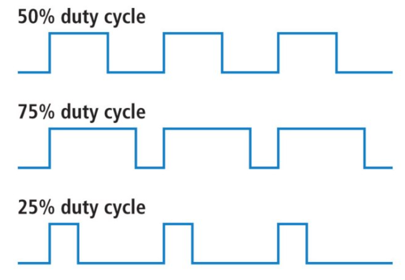
PWM Waveform Image.
Frequency of PWM in DC Operation - PWM can use a variety of frequencies for the pulses it sends, and this can alter motor behaviour and noise etc. The default frequency used for the EX-CSB1 is xxHz, but this can be varied using the virtual DCC functions 28-31 (check) to allow you to alter the frequency to better suit your loco's motor. This can of course be done during running from the throttle.
The DC PWM frequency can be set using virtual DCC Functions 28-31. Refer to the DC Mode Frequencies page for details.
Managing DCC and DC Modes in TrackManager
If you are ready to dive into customising your track outputs, TrackManager is the tool you'll use. It allows you to easily switch between DCC and DC modes for any track connected to your EX-CommandStation.
You can also set up different tracks for specific purposes, such as making one track a Booster, configuring your PROG track, or enabling Auto-Reverser mode.
For detailed steps on how to use TrackManager to change track modes and settings, check out the TrackManager page.
Hardware Requirements
These requirements are only for operating DC locomotives. There is nothing to do in a pure DCC environment where no DC or analogue locomotives are run.
Brake Pin: In order for TrackManager to operate in DC mode, the motor shield must have a brake pin defined in your "config.h" motor shield definition.
There are a very limited number of motor drivers that are known to be suitable for use with DC mode. The current list is available in the Motor Drivers List. Any other motor drivers, not explicitly listed, are not supported.
Note the EX-CSB1 has a brake pin and is therefore capable of supporting DC PWM.
Never drive from/to DC to DCC
Never drive a loco from an EX-CommandStation controlled track or district to any other DCC or DC System.
Do not attempt to connect two insulated tracks together and drive a DCC engine back and forth until someone bolder than you tries it first (or you've tested it).
Some suggested precautions are to add 4 fuses on wires (-b +b, -a +a) to the EX-CommandStation connections. Use 2A fuses for the EX-CSB1 or 5A fuses for the larger motor drivers.
Technical details
EX-CommandStation with TrackManager includes the following features:
- DCC track modes of
MAIN,MAIN_INV,MAIN_AUTO,PROG, andNONE - DC track modes of
DC,DC_INV/DCX(DC Reversed Polarity), andNONE - Booster modes (ESP32 Microcontrollers only) of
BOOST,BOOST_INVandBOOST_AUTO.
EX-CommandStation production version 5.0+ supports both DCC (PWM) and DC (PWM) Pulse Width Modulation modes as an embedded standard feature.
TrackManager allows you to set up and operate up to eight separate dual insulated sections of track/districts in either DCC (PWM) and or DC (PWM) as tracks A - H.
An Arduino Mega (with or without WiFi) and EX-CSB1, EX-CommandStation has two ready to run Tracks (A & B) which can be configured as:
- DCC (PWM) modes MAIN for mainline tracks and PROG for a programming track
- DC (PWM) modes for DC or DC_INV / DCX (opposite polarity)
- Each track/district can also be disabled by setting to "NONE"
No additional external DCC decoders are required for DC (PWM) track assignments, and a single EX-CommandStation is the only hardware needed for full functionality.
One key difference to note in comparing DCC vs. DC is that in DCC mode, forward/reverse is determined by the DCC decoder, not the track, whereas in DC mode the direction is dependent upon the track polarity.
This is not your father's DC railway which used DC transformers for Cab control.
Turn off, unplug the AC power cord, and disconnect your current DC transformer(s) / power supply(s) from the DC layout track to place in a box for safe keeping.
You will instead be using a regulated DC (Laptop) 12-16v DC 3-5Amp power supply 1 to your motor shield and or Motor Board (booster) to run all your DCC Locos and analogue DC Cabs on all your individual tracks/districts/blocks.
You will be using DC (Pulse Width Modulation PWM) to drive the DC engines, Not DC Direct Current (-0 +16v).
- The voltage you need for the motor driver depends on the scale/gauge of the layout you are using. Bigger is not always better. Too high a voltage can damage your locos. See the :ref:
reference/hardware/power-supplies:powering the motor driverfor more information.
DC Operation
When using DC mode with the EX-CommandStation, it is important to understand that this is mode does not produce the traditional varying of the DC voltage to control the speed of your locomotive. The speed of your train is controlled using a method called PWM (Pulse Width Modulation), so instead, the track always receives full voltage whenever the throttle is set above zero.
How PWM Works - PWM works by rapidly turning the voltage on and off to the track. The rate at which this happens adjusts the "effective" voltage that the locomotive's motor experiences. For example, if the voltage is on 50% of the time and off 50% of the time, the motor behaves as if it's receiving half of the full voltage. This technique is similar to how a DCC decoder controls a motor in a DCC-equipped locomotive. See the image below from Sparkfun.com for an example:
PWM Waveform Image.
Benefits of PWM in DC Operation - Using PWM for speed control has several advantages, particularly in terms of smooth operation. Trains start and stop more gradually, and running at slow speeds becomes smoother and more consistent. This gives you better control over your locomotives, making your layout more enjoyable to operate, especially during more delicate manoeuvres.
Frequency of PWM in DC Operation - PWM can use a variety of frequencies for the pulses it sends, and this can alter motor behaviour and noise etc. The default frequency used for the EX-CSB1 is 131Hz, but this can be varied using the virtual DCC functions 28-31 to allow you to alter the frequency to better suit your loco's motor. This can of course be done during running from the throttle. Refer to the function frequency table for details.
This is Not Zero Stretching
We do not support zero stretching / zero stretch address function, found on Digitrax and Lenz command Stations, on purpose. The constant dual DCC electrical signal may damage certain types of older DC motors if left on for a long time.
The Digitrax and Lenz 0 (zero) stretch DCC (PWM) signal leaves the engine lit up and humming loudly even with the throttle and engine at 0 speed, because it is receiving a Dual DCC(PWM) aka AC signal, while the EX-CommandStation TrackManager is dead quiet at rest (0 speed).
Technical Information
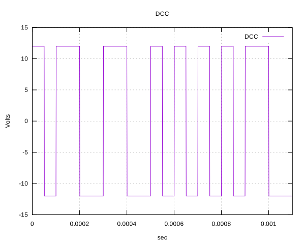
What a DCC waveform looks like
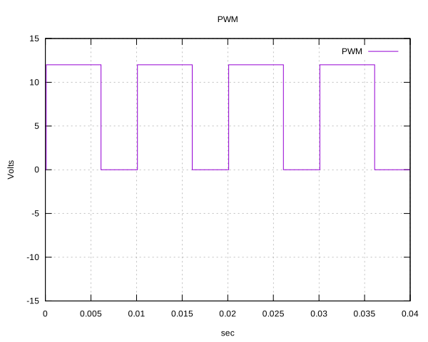
What a PWM waveform looks like
These modes, (PWM) vs analogue DC are totally incompatible with one another and if crossed will result in magic smoke and a burned out motor shield and or USB connector.
- DCC(PWM) is detected on a multimeter as an AC signal but in a square wave form, not as a sine wave
- DC(PWM) is detected on a multimeter as a DC signal in a square wave form, not as a direct current wave
The DC(PWM) track is Power supply dependent and needs a varying amount of 0 zero to maximum Vdc passed to the track of 12 or 16 or 18vdc, depending on whether they're N, HO or G scale engines.
Note: The signal is detected as DC on this track, from 0Vdc to max +xxVdc depending on the motor shield DC power supply output. The DCC-EX 122.55Hz PWM DC motor signal allows for better functioning and better running than most competing systems.
TrackManager DCC(PWM) vs. DC(PWM) wave forms
A simplified representation of what the dual (PWM) signals might look like through the track:
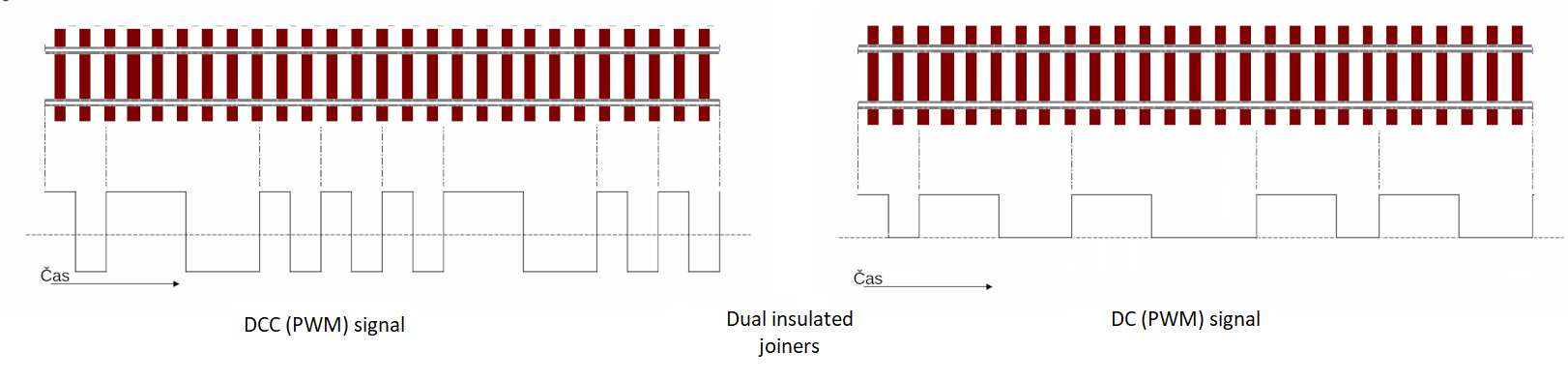
DCC PWM signal
Note on PWM frequency
Different microcontrollers utilise different PWM frequencies, and at present, these default frequencies are in use rather than using software to define them.
The side effect of these differing frequencies is that you may notice humming or sometimes squealing noises from older DC motors.
The known PWM frequencies are:
- Mega2560 - 122.55Hz
- ESP32 - 131Hz
- STM32 Nucleo - typically 1000Hz
Replacing or Integrating Into Your Current Layout
Existing analogue DC layouts which have standard DC transformers on two or more separate DC tracks/districts/blocks and/or also have a second separate proprietary DCC command station would have in place a section of dead rail, an electric relay, or a DPDT centre-off switch between the two types of controller powered stations. These should not be using a common ground rail, and only use dual insulated tracks.
You will be replacing this kind of legacy analogue DC and proprietary DCC installation described above with a single EX-CommandStation which will have a software switching implementation, allowing you to easily and quickly swap between the two DCC (PWM) and DC (PWM) modes on any of the A through H dual insulated tracks/districts in real time.
This also allows replacing the physical hardware DPDT switch.
This is all done through a single EX-CommandStation. And no we're not using another Expensive DCC decoder under the table on each Track/District/Block to address that section of track.
Do not use one of your existing loco DCC addresses
When specifying a DC or DC_INV / DCX loco ID, do not use one of your existing loco DCC addresses or road number IDs, otherwise a command sent to control a loco on that DC or DC_INV / DCX track will also operate your DCC Loco with the same address, unless you intentionally do so.
Hardware Requirements and Technical Notes
These requirements are only for operating DC locomotives. There is nothing to do in a pure DCC environment where no DC or analogue locomotives are run.
The motor driver must have a brake pin defined
In order for TrackManager to operate in DC mode, the motor driver must have a brake pin defined in your "config.h" motor driver definition.
There are a very limited number of motor drivers that are known to be suitable for use with DC mode. TThe current list is available in the Motor Drivers List. Any other motor drivers, not explicitly listed, are not supported.
Note the EX-CSB1 and EX-MotorShield8874 have a brake pin and is therefore capable of supporting DC PWM.
Do not attempt to connect two insulated tracks together and drive a DCC engine back and forth until someone bolder than you tries it first (or you've tested it).
!!! warning "Never drive a loco from/to DCC to DC.
Never drive a loco from an **EX-CommandStation** controlled track or district to any other DCC or DC System.
Some suggested precautions are to add 4 fuses on wires (-b +b, -a +a) to the EX-CommandStation connections. Use 2A fuses for the EX-CSB1 or 5A fuses for the larger motor drivers.