Infrared or IR sensors


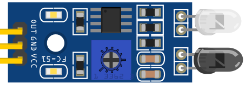
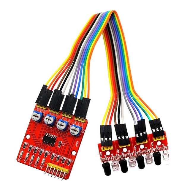
Infrared based sensors are quite prevalent and “off the shelf” varieties are very simple to implement with EX‑CommandStation and also EXRAIL as they provide a simple digital on/off output which either set their output pin low or high depending on how they are designed.
Sensor modes
There are two modes of implementing infrared sensors; reflection and beam break mode.
Reflection mode sensors
In reflection mode, the IR LED transmits the infrared light, with the sensor being activated only when an object is close enough for the IR light to be reflected back to the IR receiver. The range and success of this reflection is influenced by the colour and texture of the object, and by any natural or unnatural light sources. Reflection mode typically works best in darker lighting, with lighter coloured objects and smoother surfaces. The advantage with reflection mode sensors is they can typically be embedded within the track bed, making them easier to camouflage and less visible to the casual observer.
Beam break mode sensors
In beam break mode, the IR LED transmits the infrared light, with the IR receiver continuously receiving that light until an object passes between them, which in turn activates (or deactivates) the sensor. While this mode is still influenced by natural and unnatural light sources, beam break is typically more reliable than reflection mode provided the IR receiver is able to successfully and continuously receive the IR light without any obstructions between them. Sensors in beam break mode are typically harder to camouflage as they need to have the IR LED mounted on one side of the track and the receiver on the opposite side, which requires them to be strategically placed in trackside objects in order to hide them from view. In situations where a number of tracks run parallel, this can also present an additional challenge finding space between the tracks to mount them.
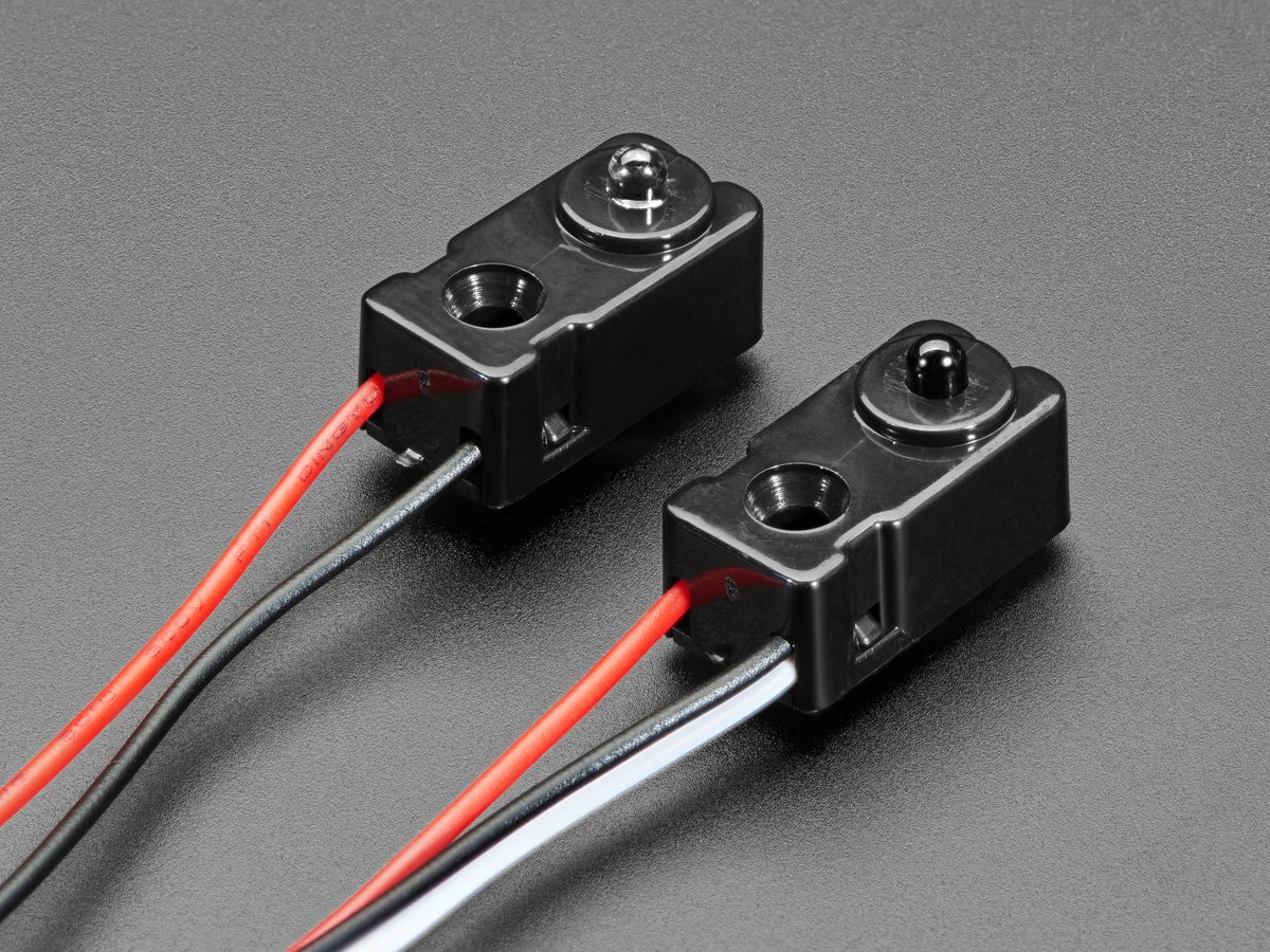
Adafruit beam break sensors
As an example, Adafruit has both a 3mm beam break  and 5mm beam break version of these sensors which hold a high level on their output (VCC) until the beam is broken when they switch to a low level (GND). Therefore these are active low sensors. These are very simple to attach to a DCC-EX command station requiring only VCC, GND and Digital input.
These are 10mm wide x 20mm high x 8mm thick, so on an HO layout this equates to 870mm x 1740mm x 696mm. Would look like a junction box next to the track.
A mount for the 3mm version is available on Thingiverse .
Like most IR break beam sensors these work best if you can angle them across the track. They work well when angled at 45deg to the track centreline about 70mm apart.
If needed the 3mm version works up to 250mm apart this allows use along a section of track. The 5mm version works up to 500mm so could be used for a track occupancy detector.
If placed at 90deg to the track centreline there can be an issue with them only sensing the wheels and activating on each wheel set that passes. Good if you want to count wheel sets or want the train to stop at a particular poin but not if your trying to only activate the sensor at the start of the train and deactivate at the end of the train.
Improving reliability
As mentioned in the sensor modes above, natural and unnatural lighting is the biggest issue with respect to the reliability of infrared sensors. Beam break mode resolves most issues, but is not always a practical solution to implement.
In order to improve the reliability of infrared sensors, particularly in reflection mode, consider implementing these mitigations:
Ensure sensors are protected from surrounding light sources
Ensure no natural light is aimed directly or (or reflected onto) the sensors
Where possible, ensure the bottom of locomotives and rolling stock is able to support reflection of the IR beam back to the receiver
There are alternative solutions that modulate the IR LED at a specific frequency (typically 38KHz like a TV remote), however these tend to be DIY solutions and typically can’t simply be purchased “off the shelf”
Modulated IR sensor software
There is a separate project that has been created to provide a software solution to the reliability issues faced with IR sensors, using both a modulated signal and a rolling comparison window to mitigate against false positives.
This project can utilise generic IR sensors available from places like AliExpress, eBay, or Amazon with a simple modification, and connects to an Arduino microcontroller to perform the modulation and the rolling window comparison. It will also integrate with EX‑CommandStation utilising the same device driver as EX‑IOExpander.
The documentation for this project is available on Pete’s Pages .
Connecting sensors
Connecting sensors will depend on the specific sensor in use, but typically this simply involves connecting the output pin to an available I/O pin either directly on EX‑CommandStation or alternatively to an I/O pin on an I/O extender device such as an MCP23017 or EX‑IOExpander.
Refer to I2C GPIO Expander Modules and EX-IOExpander for more information.
Sensor configuration for JMRI
If you are using JMRI and require these to be available as sensors, then they can be configured via the DCC-EX <Z id vpin iflag> command.
As an example, we will configure an active low sensor connected to the available I/O pin 22 on the EX‑CommandStation, and another on the first pin of the first MCP23017 device which is Vpin 164.
<S 22 22 1>
<S 164 164 1>
With these definitions, when an object comes close enough to activate a sensor in reflection mode, or interrupts the beam in beam break mode, the <Q id> response will be sent to JMRI:
<Q 22>
<Q 164>
Conversely, when the object is far enough away to not reflect the IR signal, or is no longer interrupting the beam in beam break mode, a <q id> message will be sent instead:
<q 22>
<q 164>
If these sensors are active high instead of active low, then they are configured as such:
<S 22 22 0>
<S 164 164 0>
To ensure sensors are defined at startup, refer to Startup Configuration.
EXRAIL integration
EXRAIL utilises these sensors by simply referring to their associated Vpin, and the sensor commands as outlined above are not required.
Therefore, you can simply use the standard digital sensor commands (AT, AFTER, ATTIMEOUT, IF, IFNOT, IFTIMEOUT) commands as per any other digital sensor.
When using active high sensors, adding a minus (-) sign in front of the sensor Vpin is required.
Using pin 22 on our EX‑CommandStation and the first pin on the first default MCP23017 I/O expander at Vpin 164:
AT(22)       // active low
AT(164)      // active low
AT(-22)      // active high
AT(-164)     // active high