![]()
Supported Motor Drivers


EX‑CommandStation is compatible with a wide variety of motor drivers, also known as “dual H-bridges” and “motor shields”. We’ve sorted them from least difficult to most difficult to use to help you decide what to use. When it comes to selecting a board, some considerations are size, whether it is a shield or needs to be connected with jumper wires, the amount of current you need, and whether it has current sensing capability built-in or if you have to supply it yourself.
If you have trouble finding a particular board from the list, try searching based on it’s name or the type of chip on the board and the terms “H-Bridge” or “Motor Shield”. There are often many places that sell these, especially the Chinese sites like AliExpress and Banggood.
TL;DR (aka short version): We currently recommend the DCC-EX EX-MotorShield8874, and the Arduino Motor Shield R3 or a supported clone like the Deek-Robot.
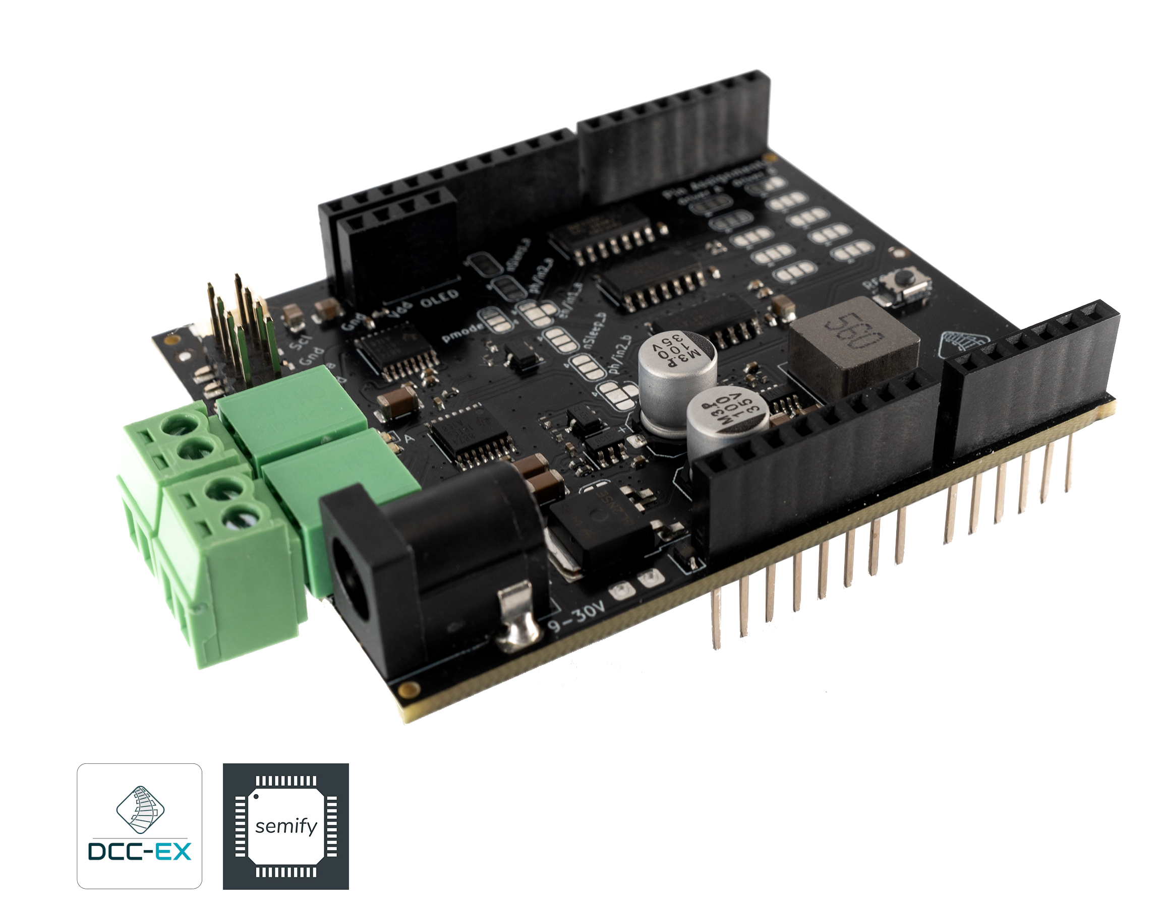
Fig 135: DCC-EX EX-MotorShield8874 RevA
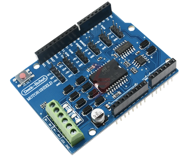
Fig 136: Deek Robot Motor Shield
Note
Where appropriate, we have used the terms “single” and “dual” to indicate on the non-shield type boards, which ones have just a single H-Bridge for one track and which ones have two. A single H-Bridge board will power your main track, but you will then need another board of some kind to connect to your programming track
What is a Motor Driver?
A motor driver (aka ‘motor controller’, aka ‘motor shield’, aka ‘motor board’) is just a high voltage, high current switch. While initially designed to power electric motors, we use it to create the DCC signal to the track in a clever misapplication of technology. Normally, a pulse width modulated (PWM) signal would be applied to a motor with the PWM pin to control speed and the direction pin would switch the voltage from positive to negative to control the motor spin direction. Instead, we send full DC track voltage to the PWM pin and switch the direction pin at the DCC frequency (around 8000 times a second) to generate the bi-polar square wave. In this way, we use the 5V DC (or 3.3V) microcontroller output to switch the voltage from separate 12-16v DC power supply [1] connected to the Motor Driver, and create a pulse train signal of 1’s and 0’s that a mobile decoder can interpret as commands.
Current list of boards
In this section we outline the various details that we know of related to each of the different boards that we’ve either tested, or know to work based on user feedback.
We’ve compiled this simple summary table to help with this:
Type / Brand |
R |
S |
Com- |
For- |
S |
Short |
Cur- |
DC |
No. |
Max |
Comments / Notes |
|---|---|---|---|---|---|---|---|---|---|---|---|
Yes |
Yes |
Conductor |
UNO / Mega |
Yes [4] |
Yes |
Yes |
Yes |
2 |
5 |
||
Yes |
Yes |
Conductor |
UNO / Mega |
Yes [7] |
Yes |
Yes |
Yes |
2 |
1.3 - 1.5 |
||
Yes |
Yes |
Conductor |
UNO / Mega |
Yes [7] |
Yes |
Yes |
Yes |
2 |
1.3 - 1.5 |
||
No |
Yes |
Tinkerer |
UNO / Mega |
No |
Yes |
Yes |
Yes |
2 |
1.3 - 1.5 |
||
No |
Yes |
Tinkerer |
UNO / Mega |
No |
Yes |
Yes |
Yes |
2 |
2 |
||
No |
Yes |
Tinkerer |
UNO / Mega |
No |
No |
No |
No |
2 |
2 |
||
No |
Yes |
Engineer |
No |
No |
No |
No |
2 |
2 |
It doesn’t have current sense |
||
No |
Yes |
Tinkerer |
No |
No |
No |
No |
2 |
15 |
|||
No |
Yes |
Tinkerer |
UNO / Mega |
No |
No |
No |
No |
2 |
3 |
current sense is not acceptable. We recommend using an external current sense board like the MAX471 |
|
No |
Yes |
Tinkerer |
No |
No |
? |
No |
1 |
5 |
|||
No |
Yes |
Tinkerer |
No |
No |
? |
No |
1 |
43 |
|||
No |
Yes |
Engineer |
UNO / Mega |
No |
Yes [5] |
Yes [5] |
No |
2 |
2 |
||
No |
Yes |
Engineer |
No |
No |
No |
No |
2 |
8 |
|||
No |
Yes |
Engineer |
No |
No |
No |
No |
2 |
2 |
|||
No |
Yes |
Engineer |
UNO / Mega |
No |
No |
No |
No |
2 |
2 |
||
VNH2SP30 - SparkFun Monster Moto and others |
- |
No |
- |
Does not work. It can’t switch fast enough to generate a reliable DCC signal |
|||||||
IFX9202ED - Infineon Dual H-Bridge |
- |
No |
- |
Does not work. Can’t switch fast enough. |
|||||||
DFRobot Romeo V2 |
- |
No |
Engineer |
- |
Well, an Engineer could perhaps get this one to work. |
||||||
Kuman Board (and any L293D based boards) |
- |
No |
- |
Does not work. Not enough current. |
|||||||
Pololu TB9051FTG based motor shield |
- |
No |
- |
Does not work. It can’t switch fast enough to generate a reliable DCC signal |
|||||||
TrackManager DC compatible boards
Warning
There are specific pin and hardware requirements in order to support DC mode in TrackManager. Use of any other board than this short list for DC mode is unsupported by the DCC-EX team.
For users wishing to use the new TrackManager DC feature, there are a very limited number of boards available for use, and only this list of boards is supported:
Easy to use boards
Intermediate boards
These boards require wiring.
Expert Level Boards
These boards require you to add your own config to the config.h file, and may not have good current sensing. That said, if you buy a separate current sense board, we particularly like the IBT_2 board (though you will need 2 of them or some other board for the programming track)
Incompatible boards
VNH2SP30 - SparkFun Monster Moto and others. It can’t switch fast enough to generate a reliable DCC signal
IFX9202ED - Infineon Dual H-Bridge. Can’t switch fast enough.
DFRobot Romeo V2 - Well, an Engineer could perhaps get this one to work.
Kuman Board (and any L293D based boards) - not enough current.
Pololu TB9051FTG based motor shield. It can’t switch fast enough to generate a reliable DCC signal. Product page
 .
.
Other boards
While not fully supported and tested, other boards can potentially be used. Look for the following criteria:
We recommend a dual h-bridge board or two discrete h-bridge boards. They can be different sizes, one bigger for main track and one smaller for programming track operations.
It must handle enough current for the layout. 2 amps will drive 3-5 HO scale locomotives.
It must have working and accurate current sensing (many do not)
It must be able to switch at least 10000 times per second (some do not)
Look for an Arduino shield form factor to eliminate wiring (not required but preferred)
Note
Current capabilities of these boards, especially the boards based on the L298 with no heat sink fins like the Arduino Motor Shield can really not deliver 2 Amps. A realistic number would be 1.5 Amps IF you added a heat sink and a cooling fan. If you need 2 Amps or more, you will need to go with a higher current board.
Configuring Motor Drivers
If your board is not in the list of supported motor driver types, or if you need to make changes or have more information about how motor drivers are configured in EX‑CommandStation, see:
High Accuracy Waveform
If you’re experiencing issues with specific decoders and all attempts to get them working are failing, you may need to enable the high accuracy waveform functionality (providing your motor driver supports it).