![]()
Overview and configuration


Note
EX‑IOExpander is currently in its infancy and as such is considered to be in Alpha testing, so could (and likely will) change without notice, and possibly even be broken in some scenarios.
Introduction
EX‑IOExpander is an additional microcontroller utilised to expand the I/O port capability of an EX‑CommandStation and connecting via I2C.
It can be used to increase the number of available pins on your command station or run devices/objects at a greater distance away from it without having to run a lot of wires back to the command station. This is accomplished by using just two I2C bus wires to connect to one or many micro controllers running the EX‑IOExpander software.
EX‑IOExpander can be used for various different functions depending on the microcontroller in use:
Reading from digital input pins
Writing to digital output pins
Reading from analogue input pins
Controlling servos via the Arduino Servo library (Uno, Nano, and Mega only)
Dimming LEDs
Rather than emulate any specific type of existing I/O expander, EX‑IOExpander has been written to integrate directly with EX‑CommandStation via its own device driver, which is how both digital and analogue pins can easily be utilised on the same device, as well as control servos and variable brightness LEDs.
This page provides the general overview of EX‑IOExpander, as well as outlining the configuration options available.
Note
Credits
EX‑IOExpander was inspired by the work of Mike B (@Springlake on Discord) and Ross (@Rosscoe on Discord) to emulate an MCP23017 device as part of a mimic panel design. The DCC-EX team have taken this inspiration and now provide a generic Arduino based I/O expander, able to utilise both digital and analogue pins.
Software requirements
To utilise EX‑IOExpander, you must be running version 5.0.0 or later of EX‑CommandStation.
In addition, you will require the EX‑IOExpander software which can be found here:
EX-IOExpander Github Repository 
Both of these can be installed via EX‑Installer, see Using EX-Installer - Detailed Instructions and Installation via EX-Installer.
Hardware requirements
EX‑IOExpander needs a dedicated microcontroller connected to the I2C bus of your EX‑CommandStation.
Refer to Supported Devices for the currently supported microcontrollers, which includes details on the pins and features available for use.
The device driver and EX‑IOExpander software are being written in such a way that should enable porting to other microcontroller architectures, and is expected to support up to 256 I/O pins. As more devices are tested and/or requested, additional devices will be supported.
Theory of operation
EX‑IOExpander can utilise digital pins in both input and output mode, and analogue pins in input mode. Digital pins in input mode can have pullups enabled or disabled.
Pins capable of both digital and analogue can be used for either purpose.
Note
To ensure the devices start with I/O pins in the safest possible state, all defined pins are set to input mode with pullups disabled by default. The pins stay in this state until they are configured explicitly via the EX‑CommandStation device driver.
As per other I/O devices, EX‑IOExpander can function with both the <S ...> sensor/input and <Z ...> output DCC-EX commands, as well as the various AT(), IF(), ATGTE(), IFGTE() type EXRAIL commands.
Servo control
There is now support for controlling servos via the Arduino Servo library for Arduino AVR platforms (Uno, Nano, and Mega only), or via hardware PWM pins on other platforms.
This enables the use of the <D SERVO ...> command, along with the SERVO(), SERVO_TURNOUT(), and SERVO_SIGNAL() EXRAIL commands, along with being able to define servo based turnout/point objects on these devices.
When using AVR based platforms that utilise the Servo library, the reported values for servo movements are from 544 to 2400, which is significantly different to the 100 to 400 in use by the PCA9685 servo modules. Experimentation will be required to determine the correct values for your servos. If you’re familiar with the library, we use the writeMicroseconds() function. Any digital pin can be used to control servos.
When using other platforms, only hardware PWM pins can be used which need values from 0 to 255, and again experimentation will be required to determine the correct values for your servos. Note that using analogWrite() and direct hardware PWM pins is not an ideal scenario for operating servos, so we would recommend considering if there is a better solution for your needs. We outline which pins have hardware PWM support available on the Supported Devices page.
For experimenting with different values for servo angles, we highly recommend trying out EX-Toolbox.
Warning
When using servos or fading LEDs with EX‑IOExpander, you must use the values as indicated above to control them, not the values documented for the PCA9685 servo modules, as those values are designed specifically for those modules.
Attempts were made to provide some sane mapping between the PCA9685 values and those required by the Servo library and hardware PWM pins, however the results were vastly different. It would be misleading to imply a value that works on one device could safely be mapped to a different value on a different and result in the same servo angle, even with the same exact servo in use.
You must also ensure you provide sufficient power to run the servos, as well as have a large electrolytic capacitor across the 5V and Ground pins to ensure servo movements don’t cause the EX‑IOExpander device to reset due to brownouts in the power supply. A capacitor in the realm of 1000uF is recommended. It is not sufficient to power the servos from the USB interface, and an external 5V power supply must be used in the same way as outlined on the Connecting a Servo Module page.
LED dimming
Dimming LEDs is also possible utilising EX‑IOExpander, enabling the use of the FADE() EXRAIL command.
Valid values for LED brightness are from 0 (off) to 255 (fully on), and any digital pin on any platform can be used.
Configuration
Aside from configuring the I2C address of your EX‑IOExpander device, the device driver loaded in your EX‑CommandStation will perform the necessary run time configuration at startup, meaning you should only ever need to update the EX‑IOExpander software when a new version is available.
Configuration changes for EX‑IOExpander are made by editing a “myConfig.h” file or writing to EEPROM if supported. An example “myConfig.example.h” file is included that can be copied and edited to suit. The only configuration item you should really need to consider is I2C_ADDRESS.
Software installation process
Installation via EX-Installer
EX‑Installer can be used to install both EX‑CommandStation and EX‑IOExpander. The process is the same for both, with the exception of the configuration options, therefore we will only outline the configuration options here. Refer to Using EX-Installer - Detailed Instructions for the full documentation on using EX‑Installer.
When you reach the “Select Product” screen, select EX‑IOExpander.
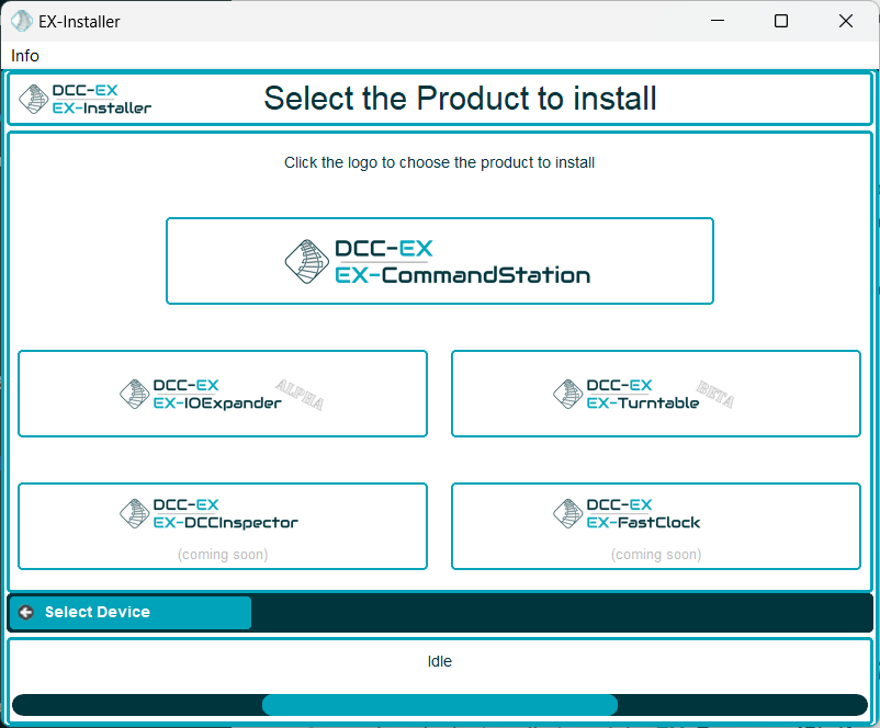
Fig 214: EX-Installer - Product Screen
We always recommend selecting the latest available version for EX‑IOExpander unless advised otherwise, but note you will only see Development versions while it remains in Alpha testing.
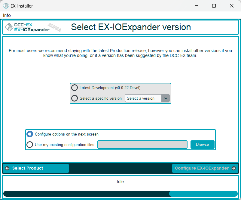
Fig 215: EX-Installer - Product Screen
Once the version has been selected, you will be able to configure the necessary options.
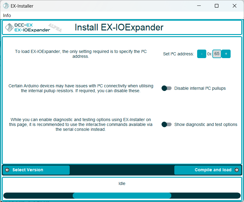
Fig 216: EX-Installer - EX-IOExpander configuration
Continue through the rest of the EX‑Installer process to load the software on to your device.
Manual installation
This is a brief overview of the software installation and configuration process:
Download the “main” branch of EX‑IOExpander
If running Nucleo or any other device without EEPROM, copy “myConfig.example.h” to “myConfig.h” and set the I2C address
Upload EX‑IOExpander to your Arduino (note, this does not get uploaded to your CommandStation)
For Arduino Nano, Uno, or Mega, use the serial console to set the I2C address
Download the “devel” branch of EX‑CommandStation
Configure “config.h”, “myHal.cpp”, and apply any required configuration changes
Upload EX‑CommandStation to your CommandStation
Configure I2C address via serial
For devices with EEPROM support (Arduino Uno, Nano, and Mega), it is possible to configure the I2C address via the serial console rather than having to update “myConfig.h”, and therefore you should be able to simply upload the software without needing to edit any files at all.
Be aware that this address will override any address defined in “myConfig.h”, and if using these devices, you do not need a “myConfig.h” file at all for normal operation.
Warning
Using the reboot <Z> command on an Arduino Nano with the old bootloader will cause it to enter into an endless reboot cycle, requiring a power cycle to recover. Pressing the reset button will not recover from the condition. Nanos with the new bootloader are fine with this command.
When using the old bootloader, use the reset button rather than the <Z> command to reboot.
There are three serial commands available to set, read, and erase the configured address, with an additional command to reboot the device:
Command |
Purpose |
|---|---|
<W address> |
This command writes the I2C address to EEPROM, for example <W 50> will set it to 0x50 |
<R> |
This will read and display the I2C address stored in EEPROM |
<E> |
This will erase the I2C address stored in EEPROM |
<Z> |
This will reboot to allow activating address changes |
Pin/Vpin allocation
Note
It has been reported that on non-genuine Arduino Uno devices (and potentially Nano) using pin D13 as an input may not work as expected due to the onboard LED causing the pin to remain low when using it as an input pin with pullups enabled. A suggested workaround is to add an external 1K pullup resistor to 5V for this pin if this is experienced.
When configuring your chosen EX‑IOExpander device, you need to know the total number of available pins, and the capability of each. Details of the pins available for use are outlined on the Supported Devices page. Vpins are allocated by the EX‑CommandStation device driver in ascending order according to the device map on this page.
Note
When the EX‑IOExpander device receives its configuration from the EX‑CommandStation, the Vpin to physical pin map will be displayed in the serial console of the EX‑IOExpander device.
For example, an Arduino Nano has a total of 22 I/O pins (D0 - D13, A0 - A7). Not all of these pins are available, and there are limitations on some pins:
D0 and D1 are used for the serial Tx/Rx pins and are therefore not available
D2 - D13 are the digital pins which are all available
A0 - A3 can be utilised as either digital or analogue pins
A4 and A5 are reserved for the I2C interface and are therefore not available
A6 and A7 can only be utilised as analogue inputs
This results in 18 pins total, with 2 pins (A6/A7) only available as analogue inputs, resulting in our pin counts and Vpin to pin map as seen on the Supported Devices page:
Total pins |
18 |
|---|---|
Digital capable pins |
16 |
Analogue capable pins |
6 |
PWM capable pins |
6 |
Vpin |
Pin |
Digital |
Analogue |
PWM |
|---|---|---|---|---|
800 |
2 |
Y |
N |
N |
801 |
3 |
Y |
N |
Y |
802 |
4 |
Y |
N |
N |
803 |
5 |
Y |
N |
Y |
804 |
6 |
Y |
N |
Y |
805 |
7 |
Y |
N |
N |
806 |
8 |
Y |
N |
N |
807 |
9 |
Y |
N |
Y |
808 |
10 |
Y |
N |
Y |
809 |
11 |
Y |
N |
Y |
810 |
12 |
Y |
N |
N |
811 |
13 |
Y |
N |
N |
812 |
A0 |
Y |
Y |
N |
813 |
A1 |
Y |
Y |
N |
814 |
A2 |
Y |
Y |
N |
815 |
A3 |
Y |
Y |
N |
816 |
A6 |
N |
Y |
N |
817 |
A7 |
N |
Y |
N |
Once EX‑IOExpander has been configured as per the sections below, you can review the Vpin allocations by running the diag command <D HAL SHOW> at the serial console, which will display this information.
This sample output is for EX-IOExpander on an Arduino Nano at the default 0x65 address and an Arduino Uno at 0x66:
<* EX-IOExpander I2C:x65 v0.0.14 Vpins 800-817  *>
<* EX-IOExpander I2C:x66 v0.0.14: Vpins 820-835  *>
Providing the device driver is configured correctly and the EX‑IOExpander device is online, the serial console of the EX‑IOExpander device will also display the Vpin to physical pin map once the configuration information is successfully received from the device driver.
This example is for an Arduino Nano configured starting at Vpin 800:
DCC-EX EX-IOExpander v0.0.23
Detected device: Nano
Available at I2C address 0x65
Servo library support for up to 12 servos
SuperPin support to dim up to 16 LEDs
Initialised all pins as input only
Received correct pin count: 18, starting at Vpin: 800
Vpin to physical pin mappings (Vpin => physical pin):
|800  =>   D2|801  =>   D3|802  =>   D4|803  =>   D5|804  =>   D6|805  =>   D7|806  =>   D8|807  =>   D9|
|808  =>  D10|809  =>  D11|810  =>  D12|811  =>  D13|812  =>   A0|813  =>   A1|814  =>   A2|815  =>   A3|
|816  =>   A6|817  =>   A7|
Viewing the Vpin map
When connected to the EX‑IOExpander device’s serial console, you can enter the command <V> to view the current Vpin to physical pin map, which will also repeat the startup display including the version, device type, and so forth as per the example above.
EX-CommandStation device driver
To enable support for EX‑IOExpander, you need to create the device in either “myHal.cpp” or “myAutomation.h” in your EX‑CommandStation. The device driver is included by default, so you simply need to create the device(s).
You will find an example included in the “myHal.cpp_example.txt” file included with the EX‑CommandStation software.
To create the EX‑IOExpander device in “myHal.cpp”, the syntax is EXIOExpander::create(vpin, npins, address); where:
vpin = An unused vpin
npins = Total number of vpins to assign to the device
address = An available I2C address (default 0x65)
Similarly, you can create the device directly in “myAutomation.h” with the command HAL(EXIOExpander, vpin, npins, address), using the same variables listed above.
Refer to the Supported Devices page to see the available pin numbers for each of the supported devices.
In the examples below, we will configure an Arduino Nano at address 0x65, with an additional Arduino Uno device at address 0x66 (note this is what provides the output seen in the previous section).
Using “myHal.cpp”:
void halSetup() {
  ...
  EXIOExpander::create(800, 18, 0x65);
  EXIOExpander::create(820, 16, 0x66);
}
Using “myAutomation.h”:
HAL(EXIOExpander, 800, 18, 0x65)
HAL(EXIOExpander, 820, 16, 0x66)
I2C_ADDRESS
/////////////////////////////////////////////////////////////////////////////////////
//  Define I2C address
//  Default 0x65, can be any valid, available I2C address
//
#define I2C_ADDRESS 0x65
The default I2C address of 0x65 should be available, however this can be changed to any available address, and must match the device driver configuration in “myHal.cpp”.
If the device has EEPROM support, and a valid address is defined in EEPROM, the address defined in EEPROM will always override the address defined in “myConfig.h”.
DIAG
/////////////////////////////////////////////////////////////////////////////////////
//  Uncomment to enable diag output
//
// #define DIAG
Uncommenting this line will enable extra diagnostic output to the serial console to help with diagnosis and troubleshooting in the event issues are encountered.
You can also configure this via the serial console using the <D> command (see Diagnostic commands).
DIAG_CONFIG_DELAY
/////////////////////////////////////////////////////////////////////////////////////
//  Delay between dumping the status of the port config if DIAG enabled
//
#define DIAG_CONFIG_DELAY 5
When DIAG is enabled, the configuration of each pin is displayed continuously to be able to monitor the configuration and state of each pin. By default, this will display every 5 seconds. This configuration item allows the delay between updates to be increased or decreased.
You can also configure this via the serial console using the <D delay> command (see Diagnostic commands).
TEST_MODE
/////////////////////////////////////////////////////////////////////////////////////
//  Enable test mode - ensure only one test mode is active at one time.
//  This is handy if serial input doesn't work for commands for some reason.
//
//  ANALOGUE - equivalent of <A>
//  INPUT - equivalent of <I>
//  OUTPUT - equivalent of <O>
//  PULLUP - equivalent of <P>
//
// #define TEST_MODE ANALOGUE_TEST
// #define TEST_MODE INPUT_TEST
// #define TEST_MODE OUTPUT_TEST
// #define TEST_MODE PULLUP_TEST
If for some reason serial input is not working as expected, test modes can be enabled via this option in “myConfig.h”.
Only enable one test mode at a time. If multiple are enabled, only the last one defined will take effect.
It is preferable, however, to use the testing commands available in the serial console.
Refer to Testing commands for details of what test each option enables and the associated serial commands.
DISABLE_I2C_PULLUPS
/////////////////////////////////////////////////////////////////////////////////////
//  Uncomment to disable internal I2C pullup resistors
//  NOTE: This will not apply to all supported devices, refer to the documentation
// #define DISABLE_I2C_PULLUPS
In cases where multiple I2C devices exist on the same bus, the pullup resistors may cause issues with reliability even the resultant resistance across all devices is too low (see Pull-ups).
In these instances, if the EX‑IOExpander device does not have physical, external pullup resistors, the internal software pullups can be disabled by uncommenting this line.
Some devices such as the Arduino Mega2560 have physical pullup resistors on the I2C pins, and therefore this configuration setting will have no effect on these devices.