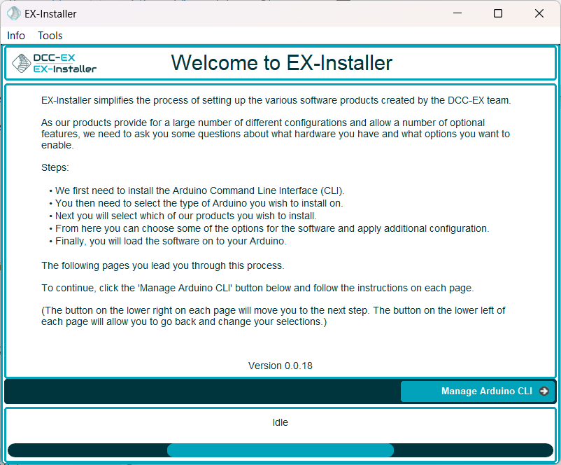
Once you have assembled your do-it-yourself EX‑CommandStation hardware you need to load our software onto it to make it usable. To make it as simple as possible we have created the EX‑Installer app.
If you already have, or wish to create, your own custom config files, we recommend that you read this page first.
Warning
We have found that there are a small number of users who can have an issue when trying to update firmware or upload EXRAIL scripts to an EX-CSB1 Command Station (or any ESP32 based device).
A word of caution on the alternate approach of using the Arduino IDE to install the software:
While it is possible install the software using the Arduino IDE, we seriouslyDO NOT RECOMMEND IT for a Conductor or Tinkerer. It is an order of magnitude more complex, much slower, and with a very high probability of getting something wrong unless you really know what you are doing.
The EX‑Installer described below will meet 100% of the needs of a Conductor or Tinkerer with considerably less effort.
Antivirus Software You may need to turn off your antivirus software before you try to install. Sometimes our software gets blocked by antivirus apps. If you see any errors on the install screen, this is usually the issue.
Find the folder in which the EX-Installer-Win64.exe or EX-Installer-Win32.exe was saved. Generally this will default to downloading to the downloads folder but your browser may be configured differently.
Right-click on the file, go to Properties, then the Permissions tab, and check “Allow executing file as program”
Open a terminal window and navigate to that folder
Run the installer with the following command: ./EX-Installer-Linux64
Important
EX-Installer creates a folder (<home>\ex-installer) to hold the information it needs. Do not directly modify anything in this folder as it a) will be overwritten or deleted by the installer at any time, and b) will cause the installer to fail to load.
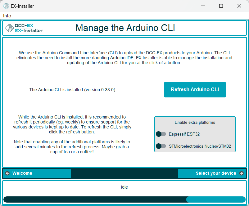
This screen allows you to install or update the Arduino Command Line Interface (CLI).
We use the Arduino Command Line Interface (CLI) to upload the DCC-EX products to your Arduino. The CLI eliminates the need to install the more daunting Arduino IDE. EX‑Installer is able to manage the installation and updating of the Arduino CLI for you at the click of a button.
If you have not installed the CLI previously you will see a Install Arduino CLI button.
If have previously installed the CLI you will see a Refresh Arduino CLI button.
If you are using an Espressif or STMicroelectronics device (including the EX‑CSB1, as opposed to the more common Uno or Mega based Arduinos, you will need to enable support for these by selecting the appropriate additional platform option.
Note
Enabling additional platforms that you will not be using will take more space on your hard drive and is likely to add several minutes to the installation process.
You must have Arduino CLI installed to proceed, simply click the Install Arduino CLI button if it is showing.
If you already have the Arduino CLI installed, it is recommended that you refresh it periodically (e.g. weekly) to ensure support for the various device details are kept up to date. To refresh the CLI, simply click the Refresh Arduino CLI button.
Installing the CLI can take some time. Maybe grab a cup of tea or a coffee!
Once the CLI is installed, To proceed, click the Select your device button.
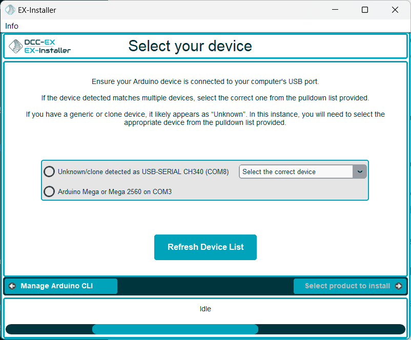
On this screen you will need to a) select the type of device you wish to load the EX‑CommandStation software onto, and b) the USB port you have connected the device to on your computer.
EX‑Installer will attempt to work out both of these for you, but it may need assistance.
When navigating to this page, a scan for devices will start automatically.
If you see No devices found it means that you either a) have not connected the device to the computer, or b) the device was not recognised by the computer.
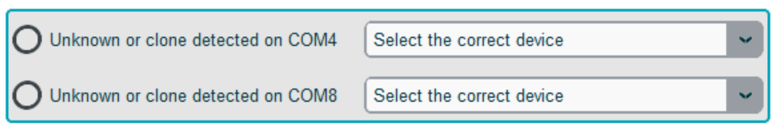
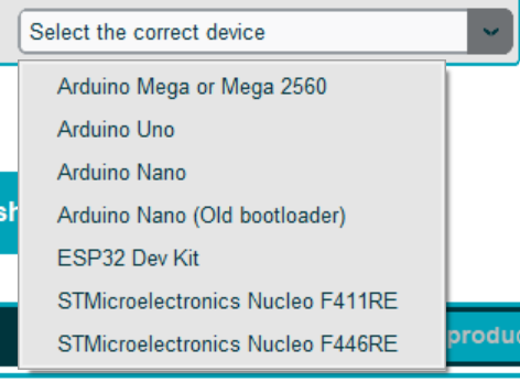
EX‑Installer will attempt to work out what type of Arduino you have connected, but in some cases it will not be able to do so. (This is especially common with cheap clone devices.)
Check and select the appropriate board from the drop down list.
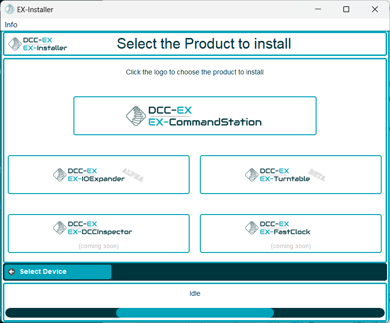
Once you have a port and device type selected, to proceed, click the Select product to install button.
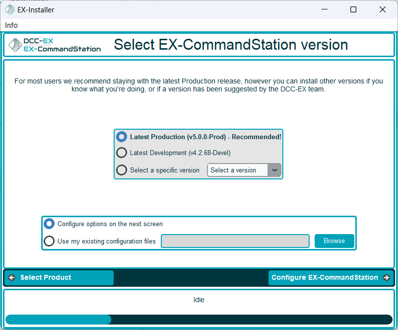
Select which version of the EX‑CommandStation software to load onto your hardware. If you are unsure, or unless you have been otherwise directed by the support team, we recommend you select LatestProduction.
Select how you wish to configure your EX‑CommandStation. Unless you are updating a previous version that you manually configured, or want to manually make advanced configuration changes, select Configureoptionsonthenextscreen
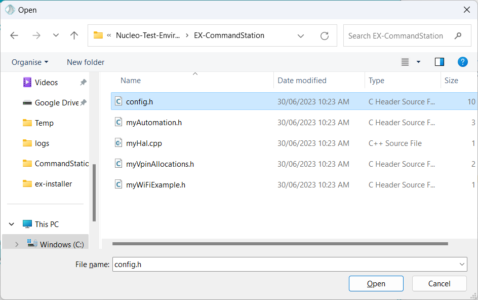
If you select Usemyexistingconfigurationfiles you will be prompted to find the folder where the configuration files are located:
Click the Browse button and navigate through your computer’s folders and files to select the location containing your existing configuration files
Select one of the files in the folder and click the Open button to select it
The chosen folder will be displayed
If you have selected Configureoptionsonthenextscreen, to proceed, click the Configure EX-CommandStation button.
If you have selected Usemyexistingconfigurationfiles, to proceed, click the Advanced Config button. In this case you will be presented with the ‘Advanced Config’ screen.
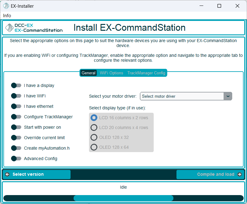
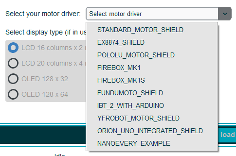
You must select the motor driver type that you have installed. The installer can’t detect this, so you must select the correct board or the EX‑CommandStation may not work.
These options are determined from the chosen version of EX‑CommandStation, and may include:
EX-CSB1
EX-CSB1_WITH_EX8874
STANDARD_MOTOR_SHIELD
EX8874_SHIELD
POLOLU_MOTOR_SHIELD
FIREBOX_MK1
FIREBOX_MK1S
FUNDUMOTO_SHIELD
IBT_2_WITH_ARDUINO
YFROBOT_MOTOR_SHIELD
ORION_UNO_INTEGRATED_SHIELD
NANOEVERY_EXAMPLE
This list will change over time as new motor drivers are added, and any older ones no longer supported are removed.
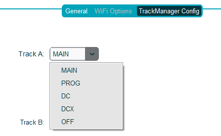
EX‑Installer does not have a simple way to configure the additional outputs so you will need to use the TrackManager feature to configure the outputs as needed in myAutomation.h in the Advanced Configuration page of EX‑Installer.
For example, to always set outputs C and D to be the second and third DCC MAIN outputs, you would create a AUTOSTART sequence that sets both outputs C and D to DCC MAIN mode in myAutomation.h.
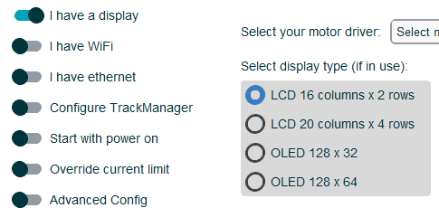
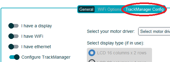
If you have installed and optional oLED or LED display, enable the Ihaveadisplay option, which will present you with a drop down list to select the type of display you have.
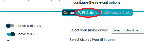
If you have installed and optional WiFi board, or are using a microcontroller board with integrated WiFi, enable the IhaveWiFi option, which will enable the WiFi Options tab, allowing you to configure the WiFi settings.
You can configure the WiFi for EX-CommandStation two ways:
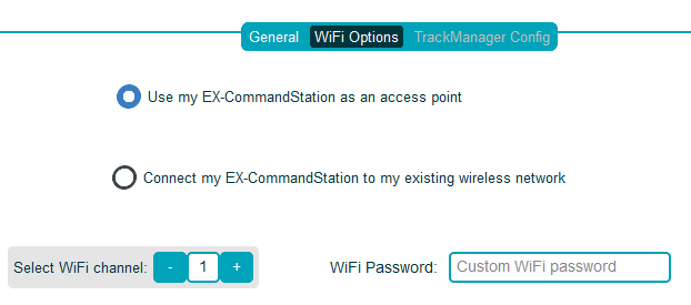
Access Point mode You can configure for EX-CommandStation to have its own, completely isolated, WiFi Network. This is referred to as Access Point Mode. (Most useful if your layout is away from the house, or you transport your layout frequently, or do not want to give guests access to your home WiFi.) To enable, select UsemyEX-CommandStationasanAccessPoint
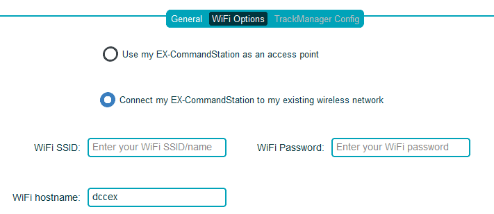
Station mode The EX-CommandStation can be setup so that it connects to your existing home WiFi Network. This is referred to as Station Mode. To enable, select ConnectmyEX-CommandStationtomyexistingwirelessnetwork
Note
For the EX‑CSB1 and DIY ESP32 based Command Stations, the Experimental / Development (DEVEL) versions of the software from 5.7.0 ignore the WiFi configuration in the config.h file. see WiFi configuration (CSB1 or ESP32 ONLY) for more information.
If possible, choose a channel that is unused (or least used) by other WiFi networks around your location.
There are numerious phone apps that can help you determine which channels are being used by other networks. For Android, ‘Wifi Analyzer’ is one that works. For iOS ‘Netspot’ is suitable (you don’t need to purchase WiPry device they mention).
If UsemyEX-CommandStationasanAccessPoint is selected, two additional options are presented:
WiFi Password
WiFi Channel
WiFi Password is optional. If this field is left blank the password will default to ‘PASS_xxxxxx’ where ‘xxxxxx’ will be the same as the SSID name that will be automatically configured.
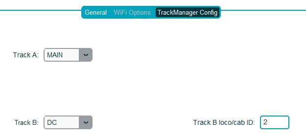
If you have selected an appropriate version of EX‑CommandStation, you will be able to enable the option to configure TrackManager. If the ConfigureTrackManager switch is disabled, you have not selected a version that includes the TrackManager feature.
Enabling this option will enable the TrackManager Config tab.
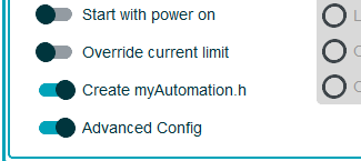
If you wish to edit the ‘config’ files directly, select this option. An additional screen will be presented for to edit the main config files.
Note there is an additional option CreatemyAutomation.h that allows a blank myAutomation.h file to be created, which you can edit on the following Advanced Config screen. Leaving this option disabled means a myAutomation.h file will not be generated if it is not required, which saves memory on your EX‑CommandStation device.
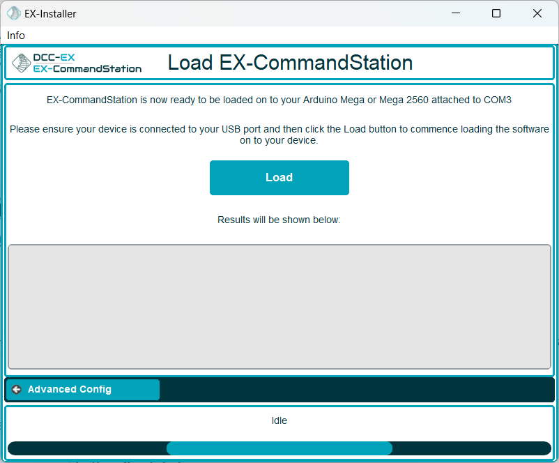
Unless you have selected Advanced Config, to proceed, click the Compile and Load button. See iv below.
If you have selected Advanced Config, to proceed, click the Advanced Config button. See iii below.
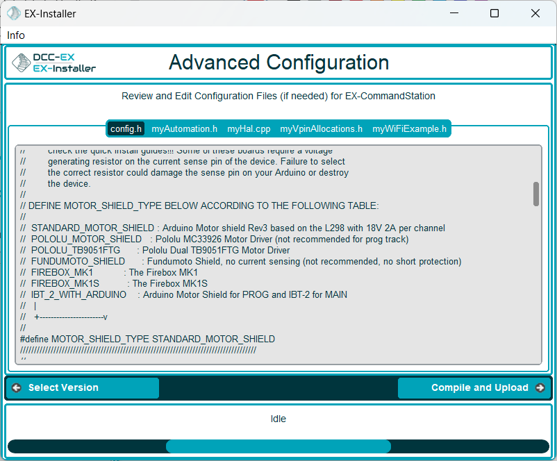
Fig 330: EX-Installer - Advance Config - more than two files
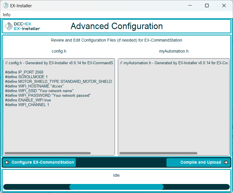
If you have selected AdvancedConfig on the previous screen, or if you chose to copy your existing configuration files, you will be presented with this screen.
On this screen you can edit the configuration files. If you have more than two files to edit, they will be separated into tabs as shown in the second figure above.
Note that if you did not enable any options requiring myAutomation.h, and did not enable CreatemyAutomation.h, you will only be able to edit config.h on this screen.
To proceed, click the Compile and Load button. See iv below.
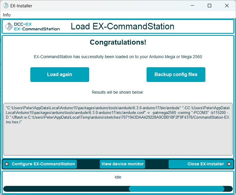
After loading the software onto your device, you can optionally copy the generated configuration files to a folder of your choice as a backup by clicking the Backup config files button.
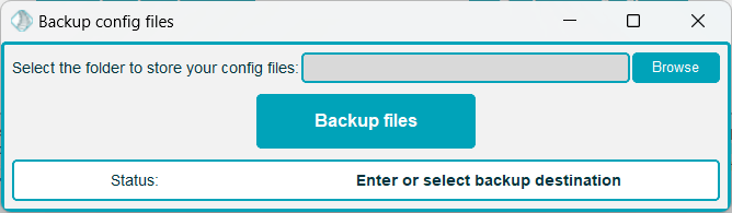
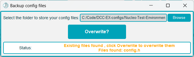
You will be prompted to select a folder, and if the chosen folder already contains config files, you can overwrite these, or you can select an alternative location.
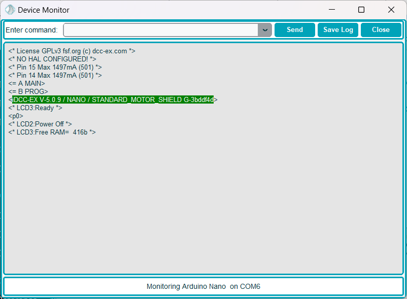
Once you have selected a device in EX‑Installer on the “Select your device” screen, or after successfully loading software onto your device, a Viewdevicemonitor button will be available.
When clicking this button, the EX-Installer Device Monitor window will open, allowing you to interact with your device by sending commands and viewing the serial console output.
The programming track is for programming only. Make sure you are on the main track if you expect your loco to move or respond to light or sound commands.