EX-WiFiShield 8266 (recommended)
AKA Makerfabs ESP8266 WiFi Shield
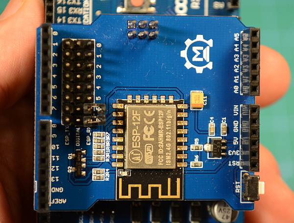
Fig 167: Makerfabs ESP8266 WiFi Shield
Installing the board follows the same procedure in the section on assembly. Start by noting the tab end of the board and align it with the tab end of the motor board. You will stack this board on top to make a three board stack.
Remove the plastic jumpers
Note the two black plastic jumpers: we need to remove both of them. You can pull them off with your fingers or needle nose pliers and either stick them in a drawer or move them to the side by having them connect via one side to any of the row of Rx pins. The other end of the connector will just hang out over the WiFi Board. If you purchase from DCC-EX or one of our dealers, you may find that they have already done this for you.
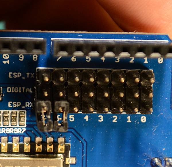
Fig 168: Remove the plastic jumpers
Align the boards
Turn the board so that the tab end is to the left and the power connectors on the other boards are to the right. You will be looking at the left side of the shield. Align it so that the pins align starting with the tab end of the boards. The Rx, Tx, 2, 3, 4, 5, 6, 7 pins on the Motor Shield line up with the 0 through 7 pins on the EX-WiFi Board. Start to get this row partially seated so all the pins are lined up with the holes. Note that there are more holes than pins. The two header holes closest to the power connectors will be empty.
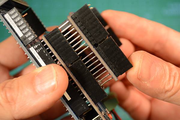
Fig 169: Get the left side pins aligned
Seat the boards
Now do the the other side. If all the pins are straight and lined up properly, hold both sides of the board and press it together gently (Fig 170:). Note that the pins are quite long and will not go all the way into the header. You should have even more of the pins showing between the bottom of the WiFi board and the top of the header on the Motor Board than between the Motor Board and the Arduino. This is normal (see Fig 171:).
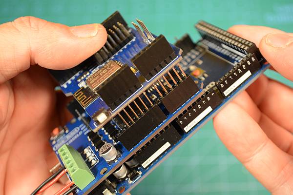
Fig 170: Get the right side pins aligned
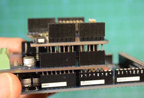
Fig 171: Fully seated boards
Install the jumper wires
We now need to connect The Transmit (Tx) and Receive (Rx) pins on the ESP8266 to the Rx and Tx pins for Serial1 on the Mega. The Mega has one serial port connected to the USB port, and then 3 extra ones we can access from pins on the board. You can think of Tx as “talking” and Rx as “listening”. That will help you remember that if one thing is talking, the other has to use its ears to listen. So we must connect the Tx of the WiFi board to Rx1 on the Mega and the Rx pin on the WiFi Board to Tx1 on the Mega.
There are three rows of pins on the WiFi shield. The middle pins each connect to one of the first 8 pins on the header. Pin 0 goes to header pin 0, pin 1 goes to header pin 1, and so on. We aren’t going to need those. With the plastic jumpers removed, nothing will be connected to any of those pins on the WiFi Board, and therefore not connected down to the Mega through the Motor Shield.
ALL of the pins in the row marked Tx (the row closest to the header) are connected to the Tx pin of the ESP8266. ALL of the pins in the row marked Rx (the row closest to the middle of the board) are connected to the Rx pin on the ESP8266.
Take a jumper wire and connect it to any one of the Tx pins on the WiFi Board, and connect the other end to the Rx1 pin on the mega (pin 19).
Take a second jumper wire and connect it to any one of the Rx pins on the Wifi Board and connect the other end to Tx1 on the mega (pin 18).
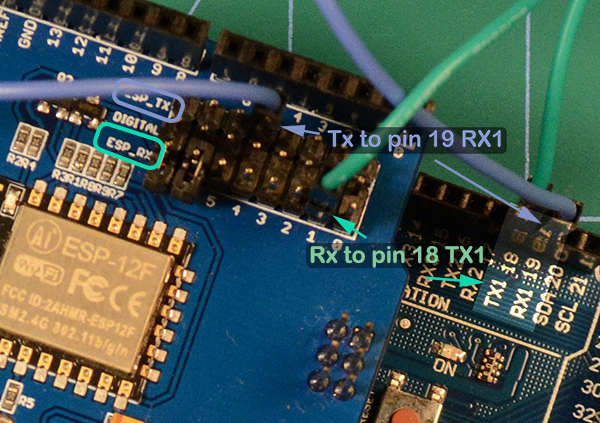
Fig 172: Install the jumper wires
Note
The screen printing on the board may make it hard to see which pins are 18 and 19, they may not be aligned exactly. Count the pins if you need to to make sure that you are using the correct ones.


