![]()
Light signals


Important considerations for light signals
When operating LEDs from any digital pins on microcontrollers or I/O expanders, it is essential that an appropriate current limiting resistor is used to protect the device from trying to source or sink too much current.
Not using a current limiting resistor will let the magic smoke out, your digital pin will become an ex-pin permanently, and if you’re really (un)lucky, you may damage your microcontroller or I/O expander permanently as well.
Defining light signal objects
To define light signal objects, this is accomplished by using the signal commands available in EXRAIL.
Note that unlike turnouts or points, there is no equivalent command available in the serial console to define signals.
The commands available are:
SIGNAL(red_pin, amber_pin, green_pin)- set the aspect by setting the appropriate pin lowSIGNALH(red_pin, amber_pin, green_pin)- set the aspect by setting the appropriate pin high
Note
The SIGNAL(...) function is used with LED’s that have the anode + leg connected to a positive v+ source.
The SIGNALH(..) function is used with LED’s that have the anode + leg connected to the output pin of a I/O device like a PCA9685 board.
Always double check that you have the appropriate Ohm Resistor(s) on the device or add them to the LED’s as needed.
What if I don’t have three aspect signals?
If you only have two aspect signals, then you can simply define the unused aspect as either “0”, or use a pin number that does not exist anywhere physically. You cannot do this with the pin number associated with the “RED” aspect, so this must always be a physical pin on your EX‑CommandStation or an I/O expander.
For example, defining a red and amber signal might look like SIGNAL(28, 30, 0). In this instance, setting the signal to red or amber will activate that light, and setting it to green will turn both red and amber off. Note, however, that if you define a signal with no amber aspect, and set it to amber, both red and green aspects will turn on.
Note if you have a single aspect signal (e.g. just red), you will have no way of turning that red signal off unless you define a virtual pin for one of the unused aspects. Using SIGNAL(28, 0, 0) will have red always lit, and setting it to green or amber will not turn it off. In order to turn the red signal off, either simply use it as a digital pin with SET(28) or RESET(28), or define a virtual pin for the unused green aspect, e.g. SIGNAL(28, 0, 5000).
What if my signals have different colours?
If your signalling requires using different colours to the standard red/amber/green, then that has no impact whatsoever on defining and operating the signals, and you will still need to refer to them as red/amber/green in the software, and control them by whichever pin is defined as the red aspect.
Signals with flashing amber
New in version 5.4
EXRAIL now has the ability to blink a vpin on and off at set intervals, which can also be utilised to creating a flashing or blinking amber signal.
This can be used with the ONAMBER(vpin) event handler to flash the amber aspect when activated.
For example, to have a signal using vpins 30 (Red), 31 (Amber), and 32 (Green) flash or blink amber when that aspect is set, you would create the signal and associated event handler in “myAutomation.h” like this:
SIGNAL(30,31,32)      // Define the signal object
ONAMBER(30)           // When amber aspect is activated
  BLINK(31,500,500)   // Turn vpin 31 on and off every 500ms
DONE
Further to this, if you wish to use both on and flashing/blinking amber, you can do so using an EXRAIL macro which can be activated as part of a route or sequence:
// Macro to flash a signal's amber aspect - assumes amber is the next vpin from the red vpin
#define FLASHAMBER(signal) \
  AMBER(signal) \
  BLINK(signal+1,500,500)

SIGNAL(30,31,32)              // Define the signal as normal

ROUTE(50, "Flash signal 30")  // Create a route to activate flashing/blinking amber
  FLASHAMBER(30)              // Call the macro defined above
DONE
Refer to BLINK( pin, onms, offms ) - Blink an output pin for further details on the BLINK() command.
Connecting the signals
There are two ways to connect light signals:
With the anode (positive) side of the lights connected to a common power source, and the cathode (negative) connected to the digital pin via a current limiting resistor - this is generally the preferred method, and is referred to as “active low” as the digital pin is set low to turn the light on
With the cathode (negative) side of the lights connected to a common ground, and the anode (positive) connected to the digital pin via a current limiting resistor - this is referred to as “active high” as the digital pin is set high to turn the light on
Active low signals
The SIGNAL(red_pin, amber_pin, green_pin) command is used when the anode or positive leg of the signal light/LED is connected to the common positive voltage source, and the cathode or negative leg of the signal light/LED is connected via a current limiting resistor to the digital pin either directly on your EX‑CommandStation, or to an I/O expander.
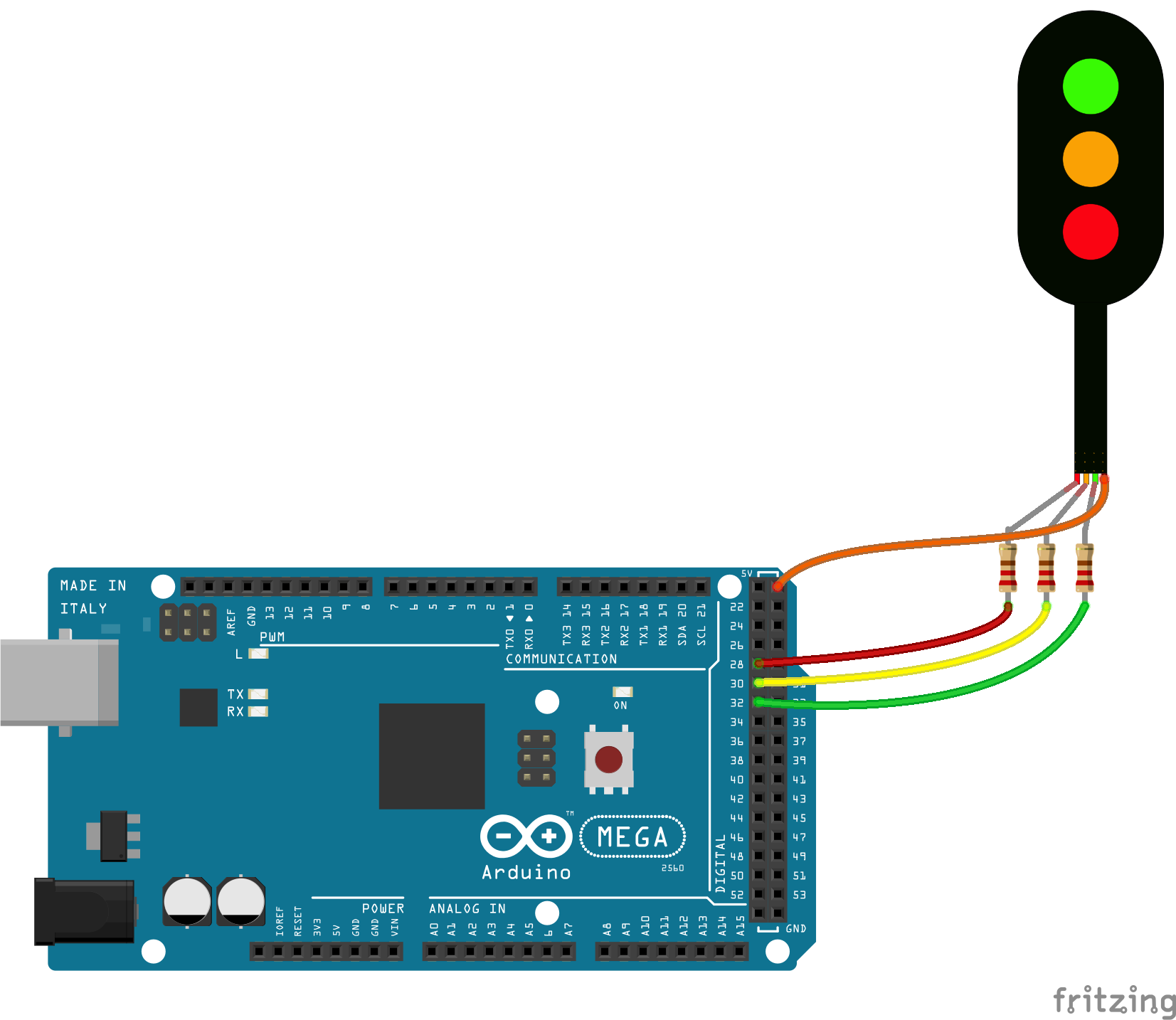
In the diagram above, the red aspect is connected to pin 28, amber to 30, and green to 32.
Sending the EXRAIL command GREEN(28) will set pins 28 (red) and 30 (amber) high, and pin 32 (green) low, ensuring the red/amber signals are off, and green is on.
Active high signals
Conversely, use the SIGNALH(red_pin, amber_pin, green_pin) command when the anode or positive leg is connected to the EX‑CommandStation or I/O expander via a current limiting resistor, with the cathode or negative connected to a common ground.
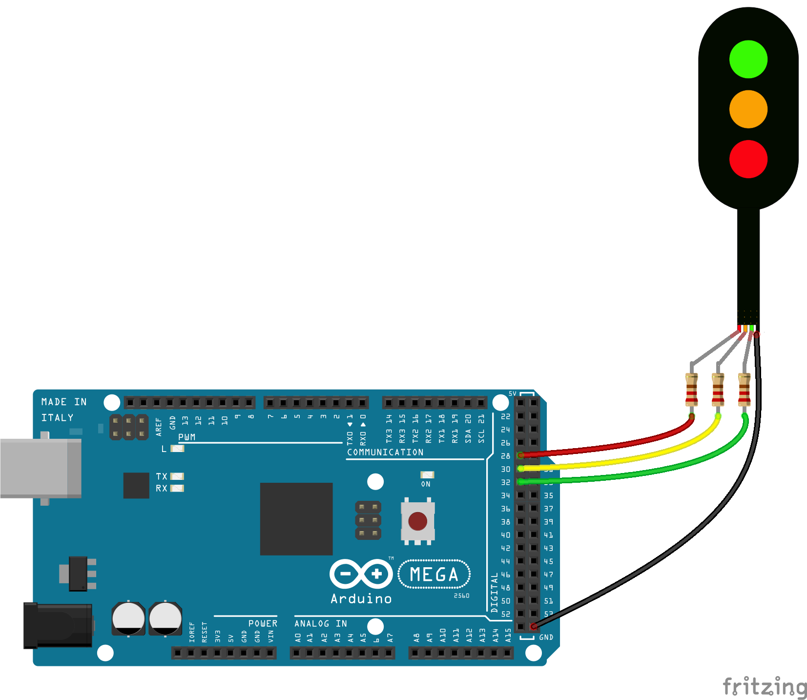
In the diagram above, the red aspect is connected to pin 28, amber to 30, and green to 32.
Sending the EXRAIL command GREEN(28) will set pins 28 (red) and 30 (amber) low, and pin 32 (green) high, ensuring the red/amber signals are off, and green is on.
Controlling light signals
Controlling light signals is exactly the same as semaphore or servo signals, skip to Controlling signals for information on controlling signals.