![]()
Mega+WiFi (Not recommended)


A WiFi EX-CommandStation with just two boards (The Mega+WiFi board plus a Motor Shield)
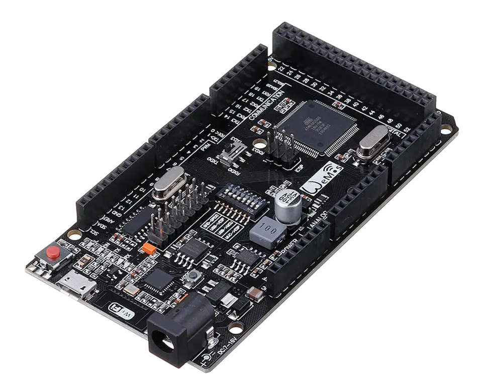
Fig 126: Mega+WiFi Board
Do you know you are going want WiFi connectivity to connect your Throttle directly to your Command Station?
Are you okay with having to throw a few switches and upload a bit of firmware onto the built-in ESP8266 WiFi chip?
The process is easy, but since in involves having to use another bit of software and requires a couple of more steps, we labelled this option for Tinkerers, but it doesn’t involve any soldering or jumper wiring.
Mega+WiFi Board is a combination of a Mega Clone and an ESP8266 WiFi chip on one board. Our guess is that like many boards made in China, this is only made by one or two factories, but sold under several names. Search for WiFi+Mega or ATmega2560+ESP8266.
Warning
Buyer beware! There have been numerous reports of build quality issues with these clone boards, with poorly soldered USB connectors and issues getting wireless working two commonly reported issues.
The DCC-EX team do not recommend the combined Mega2560 + WiFi due to the number of issues encountered in recent times.
What You Will Need
This is our tested and proven configuration
EX‑CommandStation 3.0.6 or greater
ATMega2560 + ESP8266 WiFi - Combo Board
Deek-Robot L298P Standard Motor Driver (or other approved motor driver)
12-16v DC Laptop power supply [1] to the Motor Shield (16v provides 14.5vDC to the tracks for HO Gauge)*
7-9V DC power supply to the ATmega boards with a female 2.1mm power barrel plug
Android Smartphone with Engine Driver v2.28.123 or iOS Smartphone with WiThrottle
USB-A male to Micro USB-B cable
You will also need software provided in the links below and a toothpick or small jewellers screwdriver to be able to flip small switches.
* NOTE: The L298 Based motor drivers like a Standard Motor Driver have a 1.5-2V voltage drop. More efficient boards do not have this issue. Be careful in choosing the correct voltage so that you don’t put too much voltage on the track and potentially damage your decoders.
What You Will Do
Flash the ESP8266 chip (requiring downloading of the ESP Files)
Edit your config file and Load the EX‑CommandStation v3.0.6 to the Mega2560 chip
Setup your Throttle
Note
This board uses a Micro-USB connector instead of the USB-B printer type connector used on regular Arduino Boards. It also uses the CH340G USB to Serial Driver chip instead of the FTDI on Arduino brands, so may require you to install a driver.
1. Flashing the ESP8266 chip
a. Plug in and test your Mega
Plug your board into your computer with a USB micro cable to see if it is recognised. These boards use a CH340 UART (The USB controller) instead of the ones on an Arduino brand Uno or Mega. If you have never plugged anything into your computer with this chip on it before, you are going to have to install a driver. On Windows, you can go to device manager and open the ports tree item. Look for “CH340” or “CH341”.
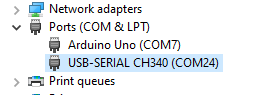
Fig 127: CH340 Recognised
If you don’t see the CH340 with the Mega plugged into USB, download and install the drivers from here:
http://www.wch-ic.com/downloads/CH341SER_ZIP.html 
Once you can see your computer recognises your board, remember the port. For a PC running windows, it will be something like “COM24” as in the picture above. For a Mac, it will be something like “/dev/cu.wchusbserial*****”, and for Linux it will look like “/dev/ttyUSBx”. Write it down.
Unplug the Mega.
For more detail on how to install the correct CH340 drivers for your OS, you can see this SparkFun Tutorial
b. Download and install the flash download tool
There are two tools you can use to flash the firmware, one is the “Espressif Flash Download tool” for Windows and the other is a Python script called esptool that will run on Windows, Mac, or Linux. Follow the path for the flash tool you choose.
Using the Flash Download Tool (Windows)
Download the Flash Download Tool and the ESP8266_NONOS_AT_Bin_v1.7.4 firmware files by clicking on the buttons below. Unzip them wherever you like:
Using esptool.py (Windows, Mac, Linux)
Download the ESP8266_NONOS_AT_BIN_v1.7.4 firmware files by clicking the button below:
Install python if you don’t already have it installed. This quick guide shows you how to check if you already have Python and how to install it if you don’t:
https://wiki.python.org/moin/BeginnersGuide/Download
Once you have Python installed, you will need to install esptool.py. Open a command prompt and use pip (or Homebrew on a macOS) to find and install it from the web:
$ pip install esptool
NOTE:with some Python installations that command may not work and you’ll receive an error. If that’s the case, try to install esptool.py with one of the following:
If you got an error about setuptools being missing, install setuptools with:
$ pip install setuptools
c. Set the switches on your Mega for flashing
With the Mega UNPLUGGED (no power connected!), you will set some switches. Use the following diagram to see the locations on the board. You can click on any picture to enlarge it.
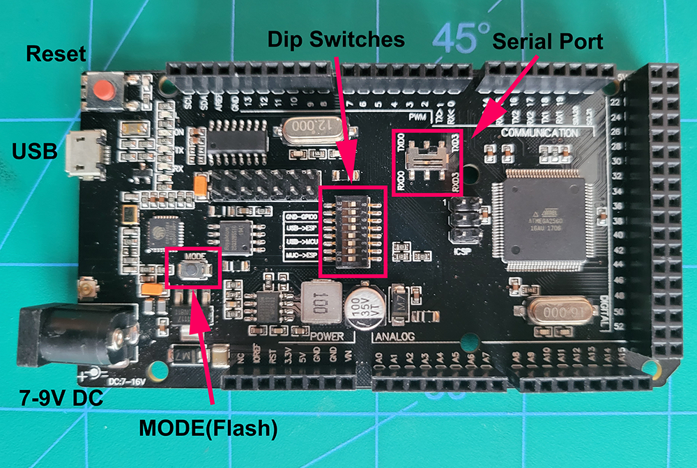
Fig 128: Important Board Locations
Note that switch 8 is not connected to anything, you don’t need to touch it. With a toothpick or jewellers screwdriver, very gently set your dip switches, it is easy to break them. Use this diagram to set your dip switches, ON is up in this picture. Switches 5,6, and 7 are on.
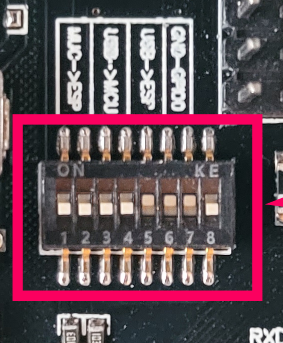
Fig 129: Switch Settings for Flashing
Use this image to set the serial port switch to RXD3/TXD3.
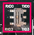
Fig 130: Switch Setting for Serial Port
Your board should be configured follows:
set dip switches 5,6,7 ON (1,2,3,4 OFF)
set Serial Port (TX/RX) Slide Pin to RXD3 & TXD3
Connect Mega+WiFi board to your computer with the USB cable
press the Mode button
d. Flash the Firmware
With the Flash Download Tool
Run the Flasher Tool
NOTE: It may take a few seconds to open while you see a black cmd window
press [Developer Mode] button
Press [ESP8266 Download Tool] button
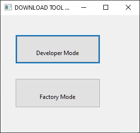
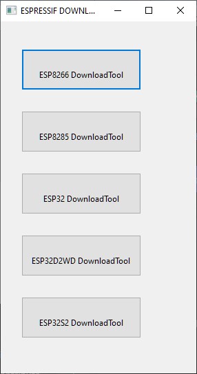
Fig 131: Flash Tool Button Selections
Setup the files and memory locations in the Flasher Tool
Click on the each file button (the “…” buttons) and find the bin files you extracted.
Follow Fig 132: and pay close attention setting up the Exact *.bin Files & locations 0xYYYYYYYY
Make sure to check all the file checkboxes to the left of the filled in file names
Set the EXACT settings using the radio buttons & baud rate settings: (26M, 40MHz, DIO, 16Mbit-C1, Your COM port selected, and 460800 baud).
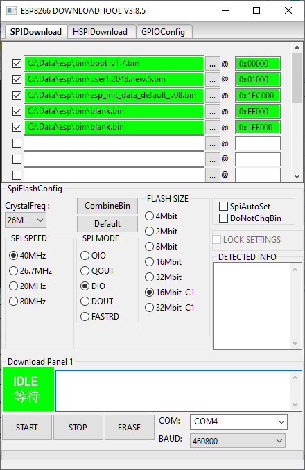
Fig 132: Flasher Settings Screen
Note
These settings are for the ESP8266EX chip on the Mega+Wifi, you may need different settings to flash an ESP-01s, ESP12, etc.
First press the Erase button and let the ESP erase the chip memory.
Then press the Start button and the bin files will flash (load) onto the ESP-WiFi chip
After flashing, the ESP8266 Log will show it uploaded them all successfully and it closes the port.
Disconnect the USB cable.
Skip ahead to e. Set the switches for run/sketch mode
With esptool.py
Unzip the firmware files found in the “bin” folder and put them in a folder so that they are easy to find. Go to a command prompt (Windows Key+R then type “cmd” and click OK, or run “terminal” on macOS) and navigate to the folder where you unzipped the firmware files. Execute the full command below from the prompt. esptool.py should be in your path and will automatically find your ESP8266 if it is connected, but we have included in the examples how to select the port. Make sure to substitute your correct port.
Linux/macOS:
esptool.py -p /dev/ttyUSB0 write_flash --flash_mode dio --flash_size 2MB-c1 0x0 boot_v1.7.bin 0x01000 at/1024+1024/user1.2048.new.5.bin 0x1fc000 esp_init_data_default_v08.bin 0xfe000 blank.bin 0x1fe000 blank.bin
Windows:
esptool.exe -p COM5 write_flash --flash_size 2MB-c1 0x0 boot_v1.7.bin 0x01000 at/1024+1024/user1.2048.new.5.bin 0x1fb000 blank.bin 0x1fc000 esp_init_data_default_v08.bin 0xfe000 blank.bin 0x1fe000 blank.bin
If there is an error, press and hold the mode button, then press and release the reset button while still holding down the mode button. Press enter to send the esptool command and let go of the mode button.
e. Set the switches for run/sketch mode
With the power disconnected from the Mega, set the switches back to the upload/run mode - dip switches 5,6,7 OFF and 1,2,3,4 ON - (Leave the TX/RX slide Pin on RxD3 TxD3) - re-connect the USB cable
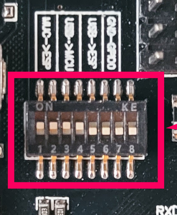
Fig 133: Switch Settings for sketch load/run
2. Decide if you want Access Point Mode or Station Mode
Access Point (AP) Mode (the default) makes the EX‑CommandStation an Access Point. That is a direct connection from your Throttle (Phone) to the EX‑CommandStation as a Local Intranet. There is no Internet access. Station (STA) Mode connects the Command Station to your local WiFi Router With Internet access. You then have to know the IP address your router assigns to the EX‑CommandStation so your Throttles (Controllers) can find it on your network.
If you choose to use Access Point (AP) Mode, there is nothing you need to do. Just make sure you select the network checkbox in the installer or rename the config.example.h file to config.h and install EX‑CommandStation. Go directly to step 5.
If you are going to want to connect to your WiFi router, you just need to enter your login information. Take a look at the Short Version of Network Setup below before proceeding to step 5. But keep in mind, you can always install, make changes, and install again.
3. Configure the EX-CommandStation Software
Short Version of Network Setup
Download and install EX‑CommandStation from by using the Automated exInstaller or using the Arduino IDE by choosing one of the links below.
How to install using the installer
Long Version of Network Setup
Long/Detailed Network Setup HERE
All settings are in the config.h file in your EX-CommandStation folder. If you don’t have a config.h, rename config.example.h to config.h.
First, make sure your dip switches are set with 1,2,3,4 ON and 5,6,7 OFF (8 doesn’t matter)
Setting up in Access Point (AP) Mode
If using the installer, just check the WiFi check box and leave SSID and password alone
If using the Arduino IDE,Make sure you didn’t put “//” in front of the #define ENABLE_WIFI true line in your config.h file
No additional changes required, Leave SSID & Passwd alone
Your ESP-WiFi chip will assign a SSID as
DCCEX_xxxxxxandPASS_xxxxxx, Where ‘xxxxxx’ is the last 6 characters of your ESP8266 MAC AddressUpload the software to your Mega+WiFi (see Compile and Re-upload below)
Setting up WiFi in Station (STA) Mode with Router
This mode is also sometimes called “Client” mode
If using the installer, select the WiFi Checkbox and enter the name (SSID) of your network and the password to log into it.
If using the Arduino IDE open the CommandStation-EX.ino file in the Arduino IDE program then
Open, then Edit & change the new config.h file to your local or home Router’s SSID & Password.
Change #define WIFI_SSID “Your network name” to the name of your local network.
Change #define WIFI_PASSWORD “Your network passwd” to the password for your network.
4. Compile and Re-upload EX-CommandStation software to the Arduino
If using the Arduino IDE, select ATMega2560 board from the “tools, boards” menu.
Select the correct COM port that sees your Mega and set baud rate to 115200
Click the upload button (the arrow pointing to the right near the checkmark in the upper left of the program window)
5. Operate Your EX-CommandStation
After the Arduino IDE uploads EX‑CommandStation sketch, make sure the serial port switch is set to RxD3/TxD3 and dip switch pins 1-4 are ON and 5-7 are OFF.
If not already connected to power, connect the Arduino ATMega2560 + ESP8266 WiFi board by Either a USB cable, or for Standalone Operations (no USB) you can use a 7-9vdc power supply in the Arduino 2.1mm female barrel jack.
When powered on through a USB cable, check the Arduino IDE Tools > Serial Monitor.
It should show the ATMega2560 & ESP8266 WiFi communicating and assigning a xxx.xxx.x.xxx IP Address and Port 2560 to the new EX‑CommandStation.
You should see ++ Wifi Setup CONNECTED ++
6. Connect your Phone as a Throttle (Controller)
If operating in Station (STA) Mode, make sure your phone is connected to your local network (The same SSID and PASSWD you set in the config.h file)
If Operating in Access Point (AP) Mode, disconnect your phone/tablet from any other network and find the SSID for your Command Station in your network list. It will be “DCCEX_xxxxxx” where the x’s are the last 6 characters of your WiFi chip’s MAC address. Use the password “PASS_xxxxxx” where the x’s are the same 6 characters.
Note
You MUST either forget your local network or turn off “auto-reconnect” for that connection when using Access Point (AP) Mode. If you do not, your phone will disconnect from the DCCEX_xxxxxx network and connect to either a stronger connection, or one that has a connection to the internet.
Start your Smart Phone (Android) Engine Driver App Or (Apple iOS) wiThrottle App and enter the IP address XXX.XXX.X.XXX assigned in the Arduino IDE Serial Monitor above and Port 2560. For Access Point (AP) Mode, it will usually be 192.168.4.1. For Station (STA) Mode, it will be whatever your router assigned it.
If the Engine Driver fails to connect the first time with the Command Station just press the Mega’s red Reset button and try the IP/Port connection again.
You should have a direct Throttle connection to the EX‑CommandStation 3.0.5+ Standalone WiFi Command Station Via your home router.
Note
This is an Operations only config, the Engine Driver Power button only powers on the Main track, Not the Prog track. Function Keys are only local Default Function Settings, and are Not transferred from the JMRI Server Roster.
Diagnosing Problems
There a few things to try if you experience issues connecting or staying connected:
Connect a Serial Monitor to the USB port and watch the boot sequence. The code will check each serial port in order to see if anything responds to an “AT” command. You will see “OK” on a line where it finds your WiFi board on serial port 3 and failure if it does not.
Confirm that you see this exact line
AT version:1.7.4.0(May 11 2020 19:13:04)
if you see any other version or date/time, then the flash did not work.
Make sure the little slide switch is set to Tx/Rx 3
Make sure you forget your local network if using Access Point (AP) Mode or set your home network to not automatically reconnect.
Try changing the WiFi Channel in your config.h file to another channel and uploading the firmware again.
Going Further
If you want to understand what is happening in more detail, such as what the different settings and firmware does, you may consult the following resources.
Detailed tutorial and analysis by DCC-EX team member Neil McKechnie (NeilMc): https://wakwak2popo.wordpress.com/2021/01/05/flashing-at-command-set-on-combined-mega-8266-board/
Fernando Koyanagi’s excellent site including a video. Just be careful not to use his settings since he used an older version of the firmware: https://www.instructables.com/Arduino-MEGA-2560-With-WiFi-Built-in-ESP8266/
The Espressif ESP8266 page (The manufacturer of the chip): https://www.espressif.com/en/products/socs/esp8266/
Espressif detailed instructions on using the esptool
https://github.com/espressif/esptool#installation–dependencies
The Mega+WiFi Schematic diagram. Click on it to enlarge:
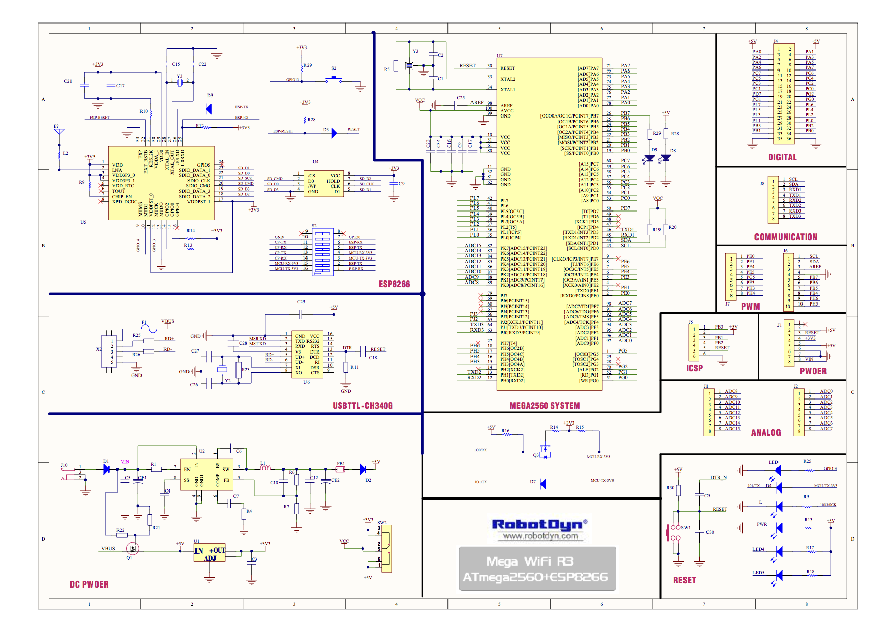
Fig 134: Mega+WiFi Schematic
Enjoy your New EX-CommandStation MEGA + WiFi On-Board Command Station!