![]()
Default Pin/VPin Allocations and Recommendations


On this page, we aim to outline and summarise the various default and recommended pins (and vpins for I/O expanders) for use with various input and output devices for our primary supported microcontrollers and I/O devices and expanders. We will also include the default I2C addresses where appropriate.
Microcontrollers
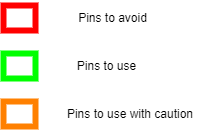
This section outlines pins to avoid, pins that are free to use, and pins that are to be used with caution for each of our primary supported microcontrollers. The pins are grouped as such:
Arduino Mega2560
Pin(s) |
Details |
|---|---|
A0 - A1 |
Analogue I/O pins used for main and program track current sensing |
3 - 4 |
Digital I/O pins commonly used by motor shields or Ethernet shields |
10 - 13 |
Digial I/O pins commonly used by motor shields |
50 - 53 |
Digital I/O pins reserved for special system utilities |
Pin(s) |
Details |
|---|---|
SDA/SCL (20/21) |
I2C connection for use with I2C displays, I/O expanders, etc., not for general I/O |
SDA/SCL (near USB) |
I2C connection for use with I2C displays, I/O expanders, etc., not for general I/O |
Tx1/Rx1/Tx2/Rx2/Tx3/Rx3 |
Additional serial ports available for use, not for general I/O |
A8 - A15 |
Analogue I/O pins available for use |
2 |
Digital I/O pin available for use |
22 - 49 |
Digital I/O pins available for use |
Pin(s) |
Details |
|---|---|
A2 - A7 |
Analogue I/O pins available by default, but may be in use for additional current sensing |
Tx0/Rx0 |
Can be used for WiFi or Bluetooth adapters but coexists with onboard USB and will need to be disconnected for software uploads |
5 - 9 |
Digital I/O pins available by default, but some motor shields or other peripherals use these |
Arduino Uno
Pin(s) |
Details |
|---|---|
A0 - A1 |
Analogue I/O pins used for main and program track current sensing |
3 - 4 |
Digital I/O pins commonly used by motor shields or Ethernet shields |
10 - 13 |
Digital I/O pins commonly used by motor shields |
Pin(s) |
Details |
|---|---|
SDA/SCL (A4/A5) |
I2C connection for use with I2C displays, I/O expanders, etc., not for general I/O |
SDA/SCL (near USB) |
I2C connection for use with I2C displays, I/O expanders, etc., not for general I/O |
2 |
Digital I/O pin available for use |
Pin(s) |
Details |
|---|---|
A2 - A3 |
Analogue I/O pins available by default, but may be in use for additional current sensing |
Tx0/Rx0 |
Can be used for WiFi or Bluetooth adapters but coexists with onboard USB and will need to be disconnected for software uploads |
5 - 9 |
Digital I/O pins available by default, but some motor shields or other peripherals use these |
I/O expanders
Note
If using an I2C LCD display with the PCF8574 backpack, it is possible that it resides at I2C address 0x27. If this is the case, you need to either not use any other devices at this address, change the PCF8574 address to 0x3F (if possible), or replace it. OLEDs typically use address 0x3C, so should not cause issues.
Refer to I2C Displays for further information.
MCP23017 digital I/O expander
MCP23017 I/O expanders have 16 digital I/O pins and 8 available I2C addresses from 0x20 to 0x27.
The device driver name is “IO_MCP23017.h”, however this is included by default.
Two devices are defined by default.
Refer to MCP23017 Modules and HAL Programming Interface for further information.
I2C address |
VPin range |
Comments |
|---|---|---|
0x20 |
164 - 179 |
Defined by default, default I2C address on some breakout boards
Some breakout boards (e.g. Waveshare or CQRobot Ocean) have 0x27 as default and will need to be changed
|
0x21 |
180 - 195 |
Defined by default, address typically needs to be configured on breakout boards |
When adding more MCP23017s, select an unused VPin that allows a total of 16 consecutive numbers for all I/O pins.
I2C address range |
VPin count |
Comments |
0x22 - 0x27 |
16 |
Need to add to myAutomation.h or myHal.cpp, and I2C address typically needs to be configured on breakout boards |
MCP23008 digital I/O expander
MCP23008 I/O expanders have 8 digital I/O pins and 8 available I2C addresses from 0x20 to 0x27.
The device driver name is “IO_MCP23008.h” and will need to be included in “myAutomation.h” or “myHal.cpp”.
Note that devices at 0x20/0x21 will conflict with the default defined MCP23017 devices at these addresses, but this conflict should be resolved automatically at startup.
Note also the potential conflict with an LCD at I2C address 0x27 as per MCP23017 digital I/O expander.
Refer to HAL Programming Interface for further information.
When adding MCP23008s, select an unused VPin that allows a total of 8 consecutive numbers for all I/O pins.
I2C address range |
VPin count |
Comments |
0x20 - 0x27 |
8 |
Need to add to myAutomation.h or myHal.cpp, and I2C address typically needs to be configured on breakout boards
May need to disable default MCP23017s if 0x20/0x21 are used
|
PCF8574 digital I/O expander
PCF8574 I/O expanders have 8 digital I/O pins and 8 available I2C addresses from 0x20 to 0x27.
The device driver name is “IO_PCF8574.h” and will need to be included in “myAutomation.h” or “myHal.cpp”.
Note that devices at 0x20/0x21 will conflict with the default defined MCP23017 devices at these addresses, but this conflict should be resolved automatically at startup.
Refer to HAL Programming Interface for further information.
When adding PCF8574s, select an unused VPin that allows a total of 8 consecutive numbers for all I/O pins.
I2C address range |
VPin count |
Comments |
0x20 - 0x27 |
8 |
Need to add to myAutomation.h or myHal.cpp, and I2C address typically needs to be configured on breakout boards
May need to disable default MCP23017s if 0x20/0x21 are used
|
PCA9685 PWM servo module
PCA9685 servo modules (or I/O expanders) have 16 PWM output pins and 62 available I2C addresses from 0x40 to 0x7D.
The device driver name is “IO_PCA9685.cpp”, however this is loaded by default.
Two devices are defined by default.
Refer to PCA9685 Modules and HAL Programming Interface for further information.
I2C address |
VPin range |
Comments |
|---|---|---|
0x40 |
100 - 115 |
Defined by default, typically default I2C address on breakout boards |
0x41 |
116 - 131 |
Defined by default, address typically needs to be configured on breakout boards |
When adding more PCA9685s, select an unused VPin that allows a total of 16 consecutive numbers for all I/O pins.
I2C address range |
VPin count |
Comments |
0x42 - 0x7D |
16 |
Need to add to myAutomation.h or myHal.cpp, and I2C address typically needs to be configured on breakout boards |
EX-IOExpander - digital and analogue I/O expander
EX-IOExpander is designed to support up to 256 pins and is currently in testing. The default I2C address is 0x65, however any valid and available address can be used.
The device driver name is “IO_EXIOExpander.h” and is included by default.
Refer to EX-IOExpander for further information.
When adding EX-IOExpander devices, select an unused VPin that allows for the appropriate number of consecutive vpins for all I/O pins.
I2C address range |
VPin count |
Comments |
Any valid/available (default 0x65) |
16 - 256 |
I2C address needs to be configured in software |
Sensors
VL53L0X time-of-flight sensor
VL53L0X time-of-flight sensors have a default I2C address of 0x29, however this address is programmable by software.
The device driver name is “IO_VL53L0X.h” and will need to be included in “myAutomation.h” or “myHal.cpp”.
Refer to VL53L0X Time of Flight Sensor for further information.
I2C address range |
Suggested first VPin |
VPin count |
Comments |
0x29 - 0x7F |
4000 |
3 |
Need to add to myAutomation.h or myHal.cpp, do not use I2C address 0x29 if using multiple devices |
Other devices
EX-Turntable
Note
EX‑Turntable is in Beta testing, however the device driver is unlikely to change much if at all.
EX‑Turntable is configured with a default I2C address of 0x60, however this address is configurable by the software.
The device driver name is “IO_EXTurntable.h” and will need to be included in “myAutomation.h” or “myHal.cpp”.
Refer to EX-Turntable for further information.
I2C address and range |
Suggested VPin |
VPin count |
Comments |
0x60 default, any valid and available I2C address |
600 |
1 |
Need to add to myAutomation.h or myHal.cpp, and use the specified version of EX‑CommandStation |