![]()
High Accuracy Waveform Mode


Do you need it? Most likely, you don’t. But if you run into a problem with a particular decoder and all the usual settings don’t help, you may want to try this mode. We have found that some older decoders do not adhere to the NMRA specification tolerances. They can fail to read bits that are within the proper range. While rare, this could occur. The High Accuracy mode makes the waveform, the pulse train of 1’s and 0’s, even tighter to the nominal values in the specification.
The nominal spec asks for 58us ‘1’ bits and 100us ‘0’ bits, with a few microseconds leeway in either direction. We opted to use 116us ‘0’ bits since it is exactly twice a ‘1’ bit, and made it easy for us to use one timer to generate both bits. On occasion, with all the other things going on inside the EX‑CommandStation, and the way we use timers and interrupts in normal accuracy mode, it is possible for there also to be a little jitter. That’s when the bit durations from bit to bit can vary a few microseconds. High Accuracy Mode uses the hardware timers instead of just our software routine, to tighten up any jitter.
For this to work, you need two things:
The signal pin for the track you want to have high accuracy must be a Timer1 pin
You must use the single signal pin configuration for your motor driver
Note
You do not have to do anything to enable High Accuracy Waveform Mode. If your motor driver config meets the above two criteria, it will be enabled automatically and report that in the Serial Monitor boot log.
The Motor Board Config
You will notice that your motor driver type is set in the config.h file. This line sets a Standard Motor Driver compatible with the Arduino Motor Driver:
#define MOTOR_SHIELD_TYPE STANDARD_MOTOR_SHIELD
Whether called Motor “boards” or “shields” or “drivers”, they are defined in the MotorDrivers.h file and look like this:
#define STANDARD_MOTOR_SHIELD F("STANDARD_MOTOR_SHIELD"), \
  new MotorDriver(3, 12, UNUSED_PIN, UNUSED_PIN, A0, 2.99, 2000, UNUSED_PIN), \
  new MotorDriver(11, 13, UNUSED_PIN, UNUSED_PIN, A1, 2.99, 2000, UNUSED_PIN)
The first line after setting the name and display text is for the Main (operations) track and the next line is for the programming (service) track. The parameters are as follows:
MotorDriver(power_pin, signal_pin, signal_pin2, brake_pin, current_pin, senseFactor, tripMilliamps, faultPin)
Therefore, the second and third parameters are the signal pins. Some boards have 2 direction pins (e.g. IBT_2 Motor Driver Board). These are sometimes labelled CW and CCW for clockwise and counter-clockwise, or LPWM and RPWM for left and right pulse width modulation. If you want to use two pins, so that you don’t need a transistor or integrated circuit inverter to take one output from the Command Station and split it into two, then you can’t use the high accuracy waveform.
If you have a board with a single DIR input, or wish to make the simple 1 transistor and 2 resistor inverter circuit shown below, you can use the high accuracy mode.
You must choose signal pins from the following list for your Arduino:
By luck, two of the Mega pins associated with Timer 1 are directly under the DIRA and DIRB pins of an Arduino Motor Driver; pins 12 and 13. Therefore, the combination of a Mega and this shield will automatically use high accuracy for both tracks.
However, an Uno’s pins do not line up with this shield. In order to use high accuracy mode, you would have to change the signal pin assignments and use a jumper wire.
Todo
LOW - Hardware  - description needed for The Motor Board Config
Inverter Circuit
Some motor boards like the IBT_2 and Wingzine boards have two separate PWM inputs, usually labeled LPWM and RPWM for left and right PWM, or CW and CCW for clockwise and counter clockwise. The following circuit will take a single PWM signal from your Command Station, split it in two, and provide the inverted signal to the second PWM pin on 2 signal input motor drivers.
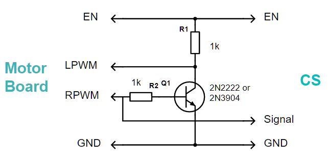
You will also have to make sure that you use a motor board definition that uses pin 11, 12, or 13 for the output signal on a Mega, or pin 9 or 10 for an Uno or Nano. For information about how to do this, see the section on Creating a motor board definition.