![]()
Connecting a Servo Module


To connect a servo module to EX‑CommandStation, you first need to get a module, based on the PCA9685 chip.
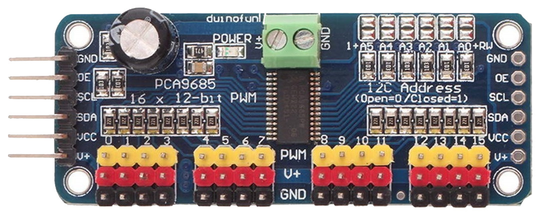
Fig 209: PCA9685 Servo Module
These are widely available from eBay, Amazon, etc. for a few dollars.
Note the pin connectors along the left side of the module - these are where you connect to the Arduino.
The 16 columns of three pins along the bottom of the module are where you connect the servos. The pins are arranged so that you can just plug a servo connector directly onto them, but be sure that the wire colours match the colours of the pins, i.e. yellow to yellow, red to red and black to black.
The servo module itself is powered from the Arduino, but the servos themselves contain motors that consume more current than the Arduino is able to supply, and so a separate 5V supply is required for the servos. This is connected to the green terminal block at the top of the module, with terminals labelled V+ and GND. The V+ terminal is connected to 5V and the GND to the 0V (ground) wire of the supply.
Connections to the Arduino are made with four jumper wires (+5V power and GND, and SCL and SDA), as shown on the following diagram:
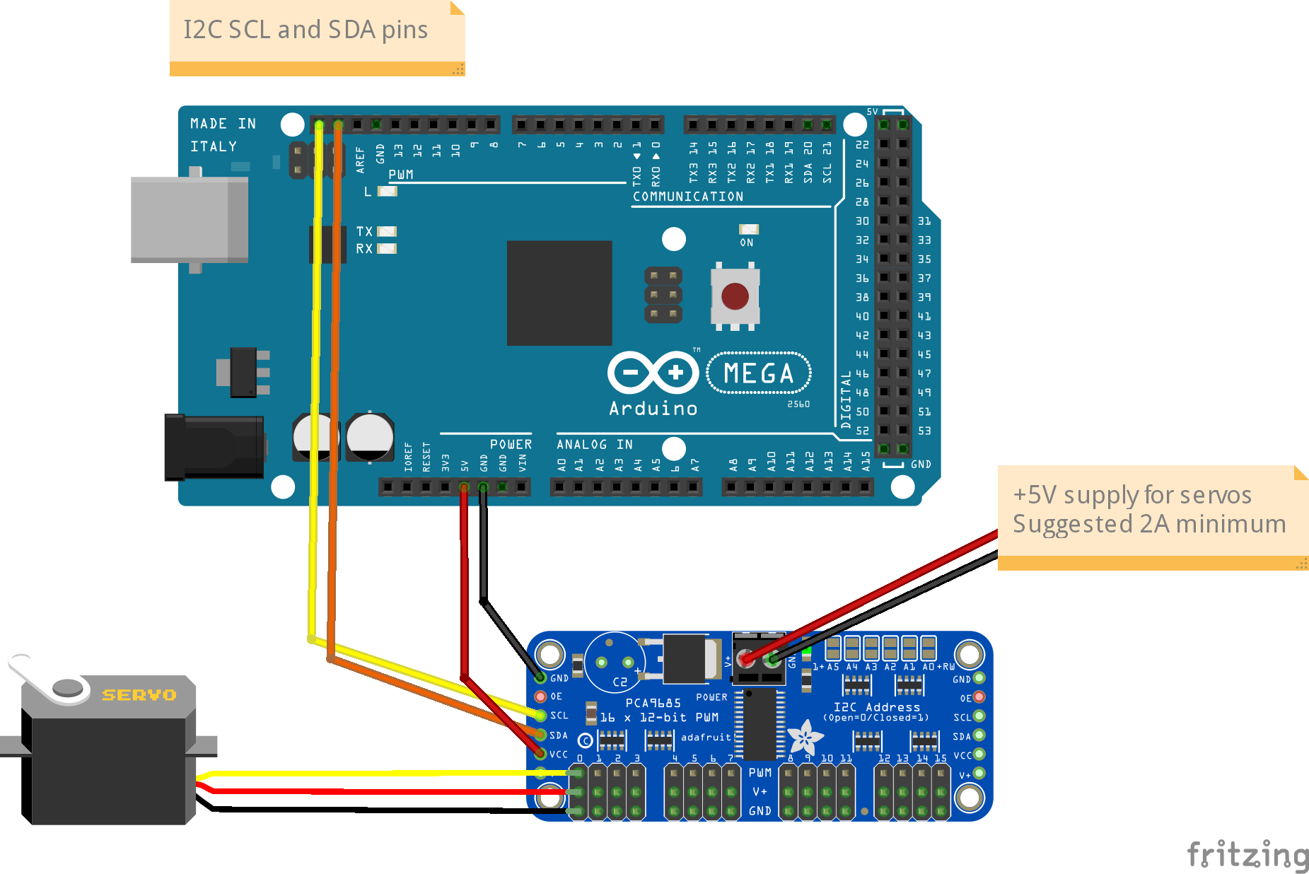
Fig 210: Mega with PCA9685 Servo Module
In EX‑CommandStation, the drivers for the PCA9685 module is already installed, and made available to for use as pin numbers 100-115. A servo is shown in the diagram, connected to the first set of pins on the module. This will be accessed using pin number 100.
Once you’ve made all of the connections, apply power to the Arduino.
Then, in the Serial Monitor, enter the command <D SERVO 100 450>. The servo should move, as long as it isn’t (by some fluke) already in that position.
Enter <D SERVO 100 110> and this time it should definitely move. For the last parameter (servo position) you can use any value between about 105 and 490.
Try <D SERVO 100 450 3> and the servo should move slowly back.
You can use the servo to control turnouts, semaphore signals, engine shed doors, and other layout components, to make your layout more dynamic and exciting. In the picture below, you can see a servo mounted below the baseboard with a piece of wire passing through a slot cut in the baseboard, to operate a turnout.
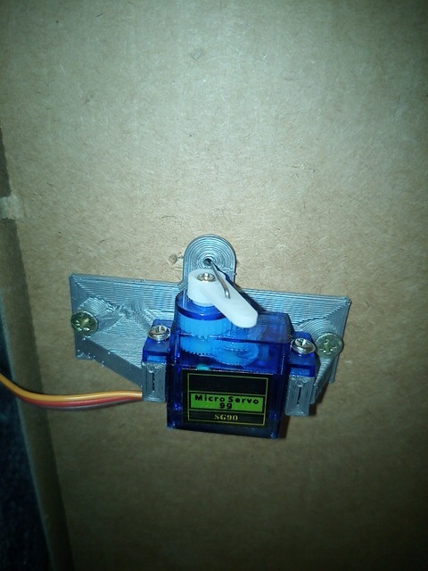
Fig 211: Servo mount to operate a turnout
And in the next picture you can see a servo that operates a semaphore signal. The signal, and its servo mounting bracket, were 3d-printed on a Creality Ender-3 printer.
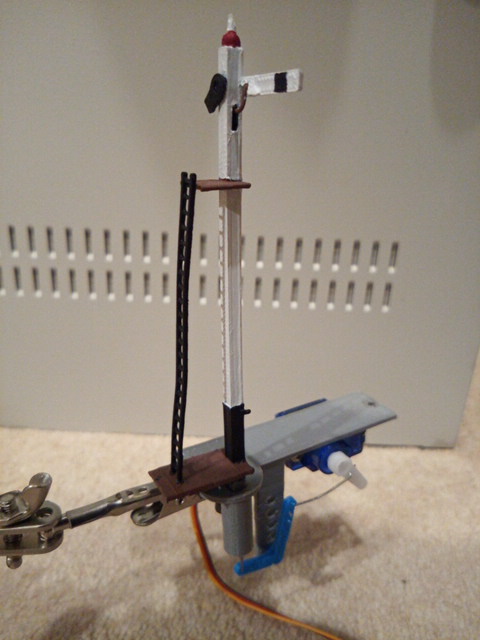
Fig 212: Servo mount to operate a Semaphore Signal
Using Servos with EXRAIL
EXRAIL supports three methods of controlling servos:
Turnouts via the SERVO_TURNOUT directive
Signals via the SERVO_SIGNAL directive
Animations via the SERVO or SERVO2 directives
Controlling servos for turnouts
The SERVO_TURNOUT directive defines a servo based turnout in EXRAIL, which will appear in wiThrottle Protocol apps, Engine Driver, and JMRI in addition to being defined as a turnout within the CommandStation.
As per the EXRAIL reference, turnouts are defined with the following syntax:
SERVO_TURNOUT(id, pin, active_angle, inactive_angle, profile [, "description"])
The valid parameters are:
id = Unique ID within the CommandStation (note these are shared across turnouts, sensors, and outputs).
pin = The ID of the pin the servo is connected to, which would typically be the VPin ID of the PCA9685 controller board.
active_angle = The angle to which the servo will move when the turnout is thrown (refer below for further detailed information).
inactive_angle = The angle to which the servo will move when the turnout is closed (refer below for further detailed information).
profile = There are five profiles to choose from that determine the speed at which a turnout will move: Instant, Fast, Medium, Slow, and Bounce (note we don’t recommend Bounce for a turnout definition).
description = A human-friendly description of the turnout that will appear in WiThrottle apps and Engine Driver. Note that this must be enclosed in quotes “”.
An example definition for a servo connected to the second control pins of the first PCA9685 connected to the CommandStation, using the slow profile for prototypical operation:
SERVO_TURNOUT(200, 101, 450, 110, Slow, "Example slow turnout definition")
Controlling servos for signals
The SERVO_SIGNAL directive defines a servo based signal in EXRAIL to drive semaphore type signals as part of sequences or routes, or simply be set via a signal or similar.
Similar to pin based signals, servo signals are controlled by the ID of the red pin only.
Unlike servo based turnouts, there is no ID or description (they don’t appear in throttles), and they use the “Bounce” profile with no other options available at the present time:
SERVO_SIGNAL(vpin, redpos, amberpos, greenpos)
A simple example using the third control pins of the first PCA9685 connected to the CommandStation would be:
SERVO_SIGNAL(102, 400, 250, 100)
Controlling servos for animations
The SERVO and SERVO2 directives allow for servos to be used in various automations within EXRAIL.
Note that unlike a SERVO_TURNOUT these are not definitions that appear within WiThrottle apps, Engine Driver, or JMRI, but are instead actions designed to be used within EXRAIL automations.
As per the EXRAIL reference, these are defined with the following syntax:
SERVO(vpin, position, profile)
SERVO2(vpin, position, duration)
The valid parameters are:
vpin = The ID of the pin the servo is connected to, which would typically be the VPin ID of the PCA9685 controller board.
position = The angle to which the servo will move when it is activated (refer below for further detailed information).
profile = There are five profiles to choose from that determine the speed at which a servo will move: Instant, Fast, Medium, Slow, and Bounce.
duration = The time (in milliseconds (ms)) for the servo to be actively rotating.
As an example, consider a lineside worker that needs to be moved away from the track when a train approaches, which is controlled by an infrared sensor.
The SERVO is attached to VPin 101 (second control pin on first PCA9685), with a sensor attached to VPin 164 (first pin on the first MCP23017):
AT(164)
SERVO(101, 400, Fast)
DONE

AFTER(164)
SERVO(101, 100, Slow)
DONE
This tells EXRAIL that when the sensor at VPin 164 is activated, the lineside worker moves quickly back from the track for safety, and then after the sensor has been deactivated, he can leisurely move back to his working position (no one wants to rush back to work right?).
Using a servo module for LEDs
Another use case for the PCA9685 is to drive LEDs using PWM to control the intensity of the LEDs. The intensity of the LEDs can vary from 0 (off) to 4095 (100%).
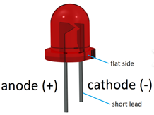
Fig 213: LED
Note
Credit to Joe Haydu for following up and summarising this info for us.
Connecting LEDs and setting intensity
LEDs can be connected with either the anode (positive) or cathode (negative) to the PWM pin of the PCA9685, and to set the required intensity for the LED, you will need to add a configuration setting to your “mySetup.h” file. Refer to Startup Configuration for further information on this file.
If connecting the anode (positive) side of the LED to the PWM pin, the cathode (negative) side connects to the ground pin, and you do not need a current limiting resistor in this scenario.
If connecting the cathode (negative) side of the LED to the PWM pin, the anode (positive) side connects to the V+ pin of the PCA9685, and you will require a 330ohm current limiting resistor.
You will need to add this line to “mySetup.h” for each LED you wish to configure:
IODevice::configureServo(vpin,OnValue,OffValue,PCA9685::NoPowerOff);
The parameters required are:
vpin = The VPin the LED is connected to, e.g. 101 for the second pin on the first PCA9685 servo module
OnValue = The desired intensity (brightness) of the LED when turned on, with 0 being off, and 4095 being 100%
OffValue = The desired intensity (brightness) of the LED when turned off
New in version 5.4
There is now an option to configure these LED’s from within the myAutomation.h file instead of the mySetup.h file. See CONFIGURE_SERVO in EXRAIL Command Reference.
Here are some examples:
// An LED with anode (positive) to PWM pin set for full intensity when turned on
IODevice::configureServo(101,4095,0,PCA9685::NoPowerOff);

// An LED with cathode (negative) to PWM pin set for full intensity when turned on
IODevice::configureServo(101,0,4095,PCA9685::NoPowerOff);

// An LED with anode (positive) to PWM pin set for half intensity when turned on
IODevice::configureServo(101,2048,0,PCA9685::NoPowerOff);

// An LED with anode (positive) to PWM pin set for full intensity turned on, and half intensity when turned off
IODevice::configureServo(101,4095,2048,PCA9685::NoPowerOff);
Using these for JMRI signal heads and signal masts
If the LEDs are to be used for signal heads or signal masts in JMRI, they can be added to the Turnout Table by defining these as outputs also in “mySetup.h”.
An output is defined by using the <Z id vpin iflag> command. Refer to Outputs (Configuring the EX-CommandStation) for further information on this command.
This command will associate the provided output ID with the LED connected to the VPin as defined in the configuration commands in the section above.
To define an output with ID 101 to match the LED connected to VPin 101, add this line to “mySetup.h”:
SETUP("<Z 101 101 0>");
Using these with EXRAIL
EXRAIL includes the FADE(vpin, value, ms) command which can is used to adjust the LED’s brightness to the provided value over the time specified in milliseconds.
The example below simulates a camp fire by continuously varying the LED brightness for random delay times, and this starts automatically when the EX‑CommandStation starts by using the AUTOSTART directive.
SEQUENCE(3)
   AUTOSTART
   FADE(101, 100, 50)   DELAYRANDOM(200,800) // Use an Amber or Red LED
   FADE(101, 500, 30)   DELAYRANDOM(200,1000)
   FADE(101,  75, 75)   DELAYRANDOM(200,400)
   FADE(101, 750, 30)   DELAYRANDOM( 50,500)
   FADE(101,  75,100)   DELAYRANDOM(100,1500)
   FADE(101, 250,100)   DELAYRANDOM(100,600)
   FADE(101, 2500, 5)   DELAYRANDOM( 50,250)
   FADE(101,  75, 75)   DELAYRANDOM(200,1000)
   FADE(101, 400, 30)   DELAYRANDOM( 50,600)
   FADE(101,  75,100)   DELAYRANDOM(200,1500)
   FADE(101, 1500,10)   DELAYRANDOM( 50,250)
   FOLLOW(3)
Technical Discussion for Engineers
There are three types of servos, standard or “Positional Rotation”, “Continuous Rotation” and “Linear”
A Standard, positional rotation servo allows a shaft to spin around a central axis to position something like an arm or disk at specific angles. A standard servo can be positioned between 0 and 180 degrees. An example is the SG90 9g Micro Servo
A Continuous Rotation Servo can spin around a full circle continuously like a motor. Instead of providing an angular position that the servo should rotate to, the continuous rotation servo simply has a speed and direction, clockwise or counter-clockwise.
Linear Servos use a rack and pinion gear that converts rotary motion to linear motion. A linear servo works just like a Standard Servo and you can control its position along a straight line, forward and back in a similar way by giving it a position.
Pulse width modulation (PWM) sends an electric pulse of variable width to the motor. With PWM there is a minimum pulse, maximum pulse, and a repetition rate. The rotor will turn to the desired position based on the duration of the pulse. When servos are commanded to move, they move to the position and hold the position. A feedback mechanism (usually a potentiometer that rotates with the shaft) adjusts the speed and direction of the motor to be able to hold the correct position.
For our analog servos, the signal or repetition rate is 50Hz, that is once every 20 milliseconds (ms). The duration of the pulses are between 544 and 2400 microseconds (µs) representing 0 and 180 degrees. To derive our 12-bit PWM value, we divide the pulse durations by 20ms and multiply by 4096. That gives us a range of 111 to 491.
Another way to look at this is that with our 12bit ADC (Analog to Digital Converter), which can measure from 0 to 4095, 4096 (100%) is 20ms pulse length and 0 (0%) is 0ms pulse length. We convert 4095 to 100% since you can’t represent the value 4096 in 12 bits.
Note
It is a bit difficult finding datasheets for different servos. For the SG90, we have seen a range listed of 1000-2000µs, which maps to 205-410, and 500 to 2400µs, which is 102 to 490. You define these in JMRI, or in the command station in mySetup.h or via command with “<T id SERVO vpin thrownPos closedPos profile>”.
Tip
Keep a spare slot (we recommend 100) open on your first PCA9685 board so that you can test servo positions with the <D SERVO …> command to connect your servos to and get the exact positions you need.
Servo motors have three wires: power, ground, and signal. The power wire is typically red, and should be connected to the an external 5V power supply. Do NOT connect this to the 5V power of the Arduino! The ground wire is usually black or brown and connects to a ground pin. The signal pin is typically yellow, orange or white and should be connected to a digital pin of the PCA9685.