![]()
ESP-01 and ESP-01s


This is the board that started it all. It fuelled the WiFi revolution in small devices. In fact, this little board is actually a microcontroller that is more powerful than the Arduino Uno! The difference between the 01 and the 01S is primarily that there is more memory on the 01-“S”. Since the 01 version has been retired, any new board you get should be the 01s, but either will work.
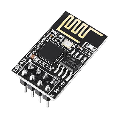
Fig 174: ESP-01s
Warning
Please be aware that the Espressif firmware shipped with Duinopeak ESP8266 WiFi Expansion and ESP-01 or ESP-01S devices will probably NOT work with EX‑CommandStation out of the box.
(Note: The recommended Makerfabs ESP8266 WiFi Shield is now shipping with the correct firmware version and will work with EX‑CommandStation without modification).
This can be corrected, but is probably beyond Conductor level and requires additional hardware.
See ESP8266 (WiFi Boards) - AT Version Issues and Solutions for details on how to check the version and how to correct it if needed.
Install the Module
Below is a wiring diagram for connecting the ESP8266 to the Arduino. For clarity, the image does not show the motor board already on top of the Mega, but since the headers connect all the pins together vertically, you can find the same pins on the motor board to get the 3.3V and Gnd to power the ESP8266.
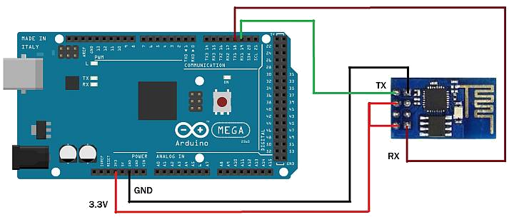
Fig 175: Wiring an ESP-01s to a Mega
Wiring
Arduino   ESP8266
3.3V -----> Vcc
3.3V -----> CH_PD
Gnd  -----> Gnd
Tx   -----> Rx
Rx   -----> Tx
In order to connect both Vcc and CH_PD to the 3.3V output of the Arduino, you can make a “Y” shaped jumper or put the ESP-01s on a small circuit board and wire it that way. Below are little boards you can buy called “ESP-01 Breakout Board” or “ESP-01 Breadboard adapter”. Some even have a voltage regulator so you can use the 5V power from the Mega instead of 3.3V, and “level shifters” to adapt the IO pins from 5V to 3.3. We highly recommend these little boards. In esp-01s-adapters below, the board on the left is just a plain breadboard adapter. The other two boards have the regulator and logic level shifters.
Note
About current requirements: While we at DCC-EX Labs have had success with running the ESP-01s off the 3.3V Mega power supply, this is at the limit of what the Mega can supply. The Mega 3.3V regulator is only rated for 200mA. The ESP can exceed this in short bursts. If you want to be safe, you can power a 5V to 3.3V regulator from the 5V supply, or find another way to provide clean, regulated 3.3V to the ESP.
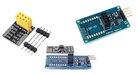
Fig 176: ESP-01 Breakout Boards
Warning
The ESP8266 chips are designed for 3.3V. DO NOT TRY TO CONNECT THEM TO 5V!! While they cannot handle 5V for power, their GPIO pins are 5V tolerant. Because of this, you don’t need any additional circuitry. However, to be safe, you can use a small level shifter board  , or use one of the breakout boards like the one above and to the right that has a 3.3V regulator and level shifters for the Tx and Rx pins.