![]()
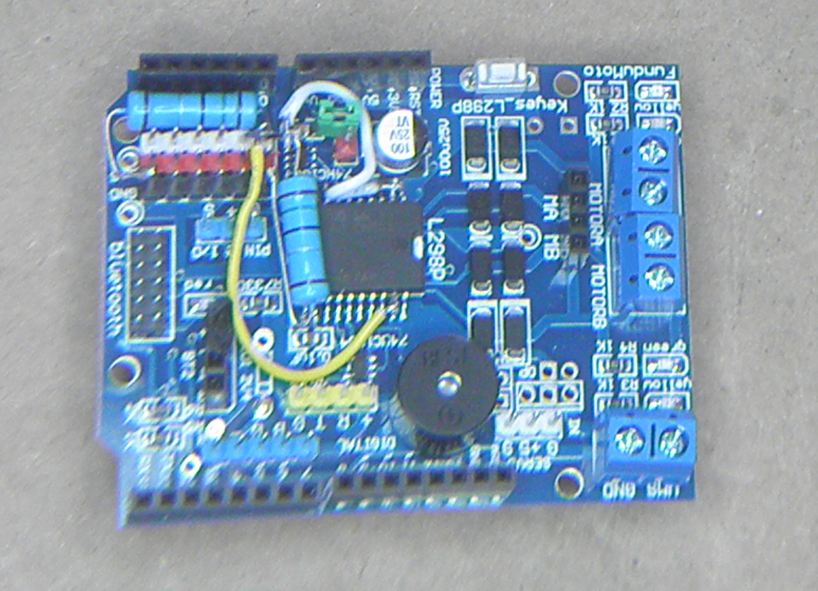
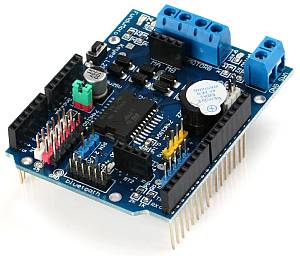
Keyes/Fundumoto (“Beeper Board”)


Warning
This board is not compatible with TrackManager DC mode.
THIS BOARD HAS NO CURRENT SENSE! Refer to the Current Sense and Sense factor section for further information.
You have to lift two traces and solder 2 resistors and use 2 jumpers to the current sense pins. This board is immediately recognizable because it has a cylindrical beeper or buzzer on the board.
To modify the beeper board, de-solder legs 2 and 19 off the solder pad, bend the legs up away from the PCB, and solder a wire directly to the legs. Be sure the legs of the IC are no longer in contact with the PCB, nor other legs.
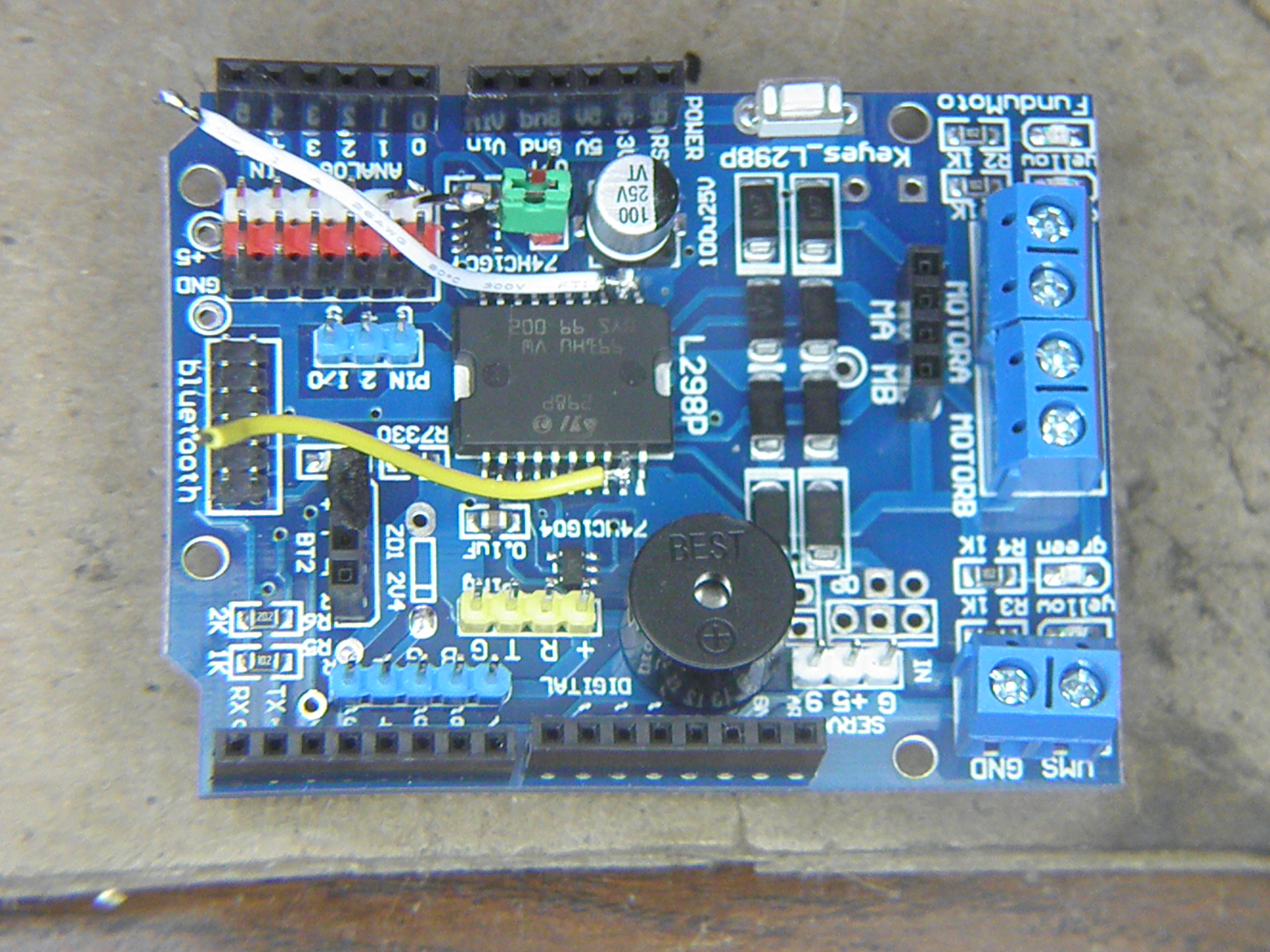
Solder the other end of each wire to the correct white header post. These correspond to A0 and A1, with pin 2 of the IC connecting to A0, and pin 19 to A1.
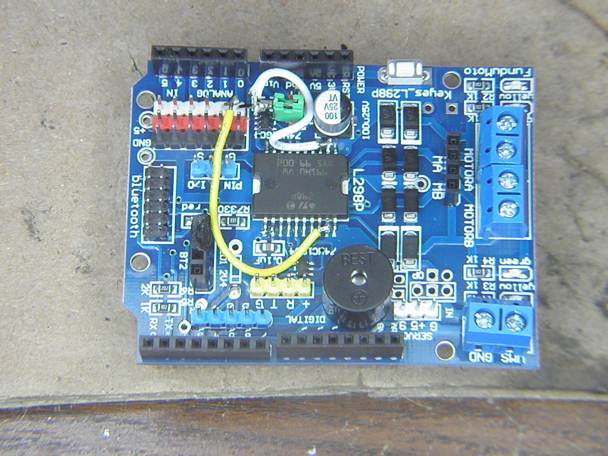
Solder one end of a 1.5 ohm, 3 watt resistor to each of these same header pins, and the other end to the corresponding black header pin (ground). Once done, your board now has current sense capability.
Warning
Check your work!
When modifying any board like this, it’s important to test what you’ve done before applying any power. You should use a multimeter to ensure the pins desoldered to not have short circuits to any other pins, as well as ensuring you haven’t accidentally bridged any header pins together with your soldering. You should also validate that each pin measures 1.5ohms to ground. An open circuit means you haven’t soldered them correctly, and a zero ohm reading means they’re still connected to ground directly.