![]()
I2C Devices


With the advent of the Hardware Abstraction Layer (HAL), EX‑CommandStation now has the capability for software support for new I/O devices to be added without any change to the base software. By I/O devices I mean the things that are controlled through Displays, Sensors, Outputs and Turnouts (and more recently by commands in EXRAIL too). Motor shields are not included in the HAL at present.
As a consequence of this, it is much easier to write a device driver for a new device, without the risk of breaking EX‑CommandStation for other users. There are various drivers already available for you to use:
I2C-connected Displays (LCD, OLED);
support for multiple LCD/OLED displays;
I2C-connected GPIO Expanders (MCP23017, MPC23008, PCF8574);
I2C-connected Servo Controller (PCA9685);
I2C-connected laser proximity detector (Time-of-Flight) (VL53L0X);
I2C-connected Analogue input modules (ADS111x);
I2C Multiplexers support (TCA9547, TCA9548);
Serial-port-connected DFPlayer MP3 player;
Ultrasound proximity detector (HC-SR04);
and others.
You will have noticed that a lot of the devices above have the name I2C in their description, so this section is an introduction to what I2C is and how to use it.
What is I2C?
I2C is a standard introduced by the Philips Semiconductors (now NXP Semiconductors) in the early 1980s to provide a mechanism for simple and economical communication between integrated circuits within a system, i.e. Inter Integrated Circuit (or IIC, or I-squared-C; hence I2C). The term I2C was originally under copyright, so other manufacturers sometimes use the term Two-Wire Interface (TWI).
I2C uses two bus wires (and the components share a ground and usually a power wire). One bus line is called SCL (clock) and the other is SDA (data). Both wires are pulled up to the power supply level (+Vcc) through a resistor, so when inactive, the wire is HIGH state (Vcc).
All I2C devices are connected to both the SDA and SCL lines, so are able to see whether the lines are pulled up (HIGH state) or pulled down (LOW state). Any device may activate one or the other line by connecting the wire to Ground, so that all of the other devices see a LOW state. The data is presented on the SDA line, bit by bit, in sync with the pulses on the SCL line.
The master is responsible for generating the clock signal on the SCL line, whether the Master is transmitting or the Slave is transmitting. Clock speeds for the Arduino are generally either 100kHz (Standard mode) or 400kHz (Fast mode). Other speeds may be selected, but the Arduino AVR microcontroller will not operate at speeds faster than 400kHz.
One device on the bus is termed as the MASTER. Only a Master device is able to initiate communications on the bus. The bus may also have a number of SLAVE devices. The slave only speaks when it is spoken to by a Master.
Note
The I2C standard allows for multi-master buses in which two or more Master devices may be present. EX‑CommandStation only has a single Master, which is the EX-CommandStation controller itself.
Each Slave device has an address on the bus, which is normally 7 bits in length. I2C addresses are generally written in hex format, in the range 0x00 (0) to 0x7F (127). For example, a GPIO Expander device might have an address of 0x20, and an OLED display may be 0x3F.
Note
The addresses in the ranges 0x00 to 0x0f and 0x78 to 0x7f are reserved, and should not be used for devices. Also, the I2C standard allows for 10-bit addresses, but none of the devices currently used by EX‑CommandStation support this.
When the Master wants to communicate with a Slave device, it sends the address of the device it wishes to communicate with, and a Slave device which matches that address will respond. The Master may then send further data which that Slave may interpret as a command. Or the Master may wait to allow the Slave to send data. In this way, we can have two-way data flows from Master to Slave, and from Slave to Master.
For more information about I2C, including a link to the I2C Standard, see https://www.i2c-bus.org/  .
.
Addresses
Most I2C devices allow the address to be selected by adding or removing (or moving) jumpers. In some cases the jumpers are fitted on selector pins on the module, and the jumpers can be readily moved to select the address. For example, the MCP23017 can have address 0x20, 0x21, 0x22, … up to 0x27, by three jumpers. The PCA9685 has a whopping six jumpers, allowing the address to be selected from 0x40 up to 0x7F (although addresses 0x78 to 0x7F should not generally be used). Some modules, like the PCA9685, use solder jumpers, which are pairs of pads on the PCB that have to be bridged by a solder blob. OLED Display modules typically have only one pair of solder pads which allow the address to be selected to 0x3E or 0x3F (default 0x3F).
The image below shows a PCF8574 module, which has three yellow jumpers labelled A0-A2, currently shown in the right-hand position marked ‘–’ (=OFF). This means the address is set to 0x20. If we move all three jumpers to the left-hand position (‘+’=ON), then the address will be 0x27.
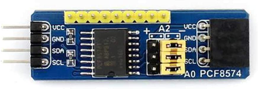
Fig 191: PCF8574 GPIO Expander Module
Address |
A2 |
A1 |
A0 |
|---|---|---|---|
0x20 |
OFF |
OFF |
OFF |
0x21 |
OFF |
OFF |
ON |
0x22 |
OFF |
ON |
OFF |
0x23 |
OFF |
ON |
ON |
0x24 |
ON |
OFF |
OFF |
0x25 |
ON |
OFF |
ON |
0x26 |
ON |
ON |
OFF |
0x27 |
ON |
ON |
ON |
The same address settings apply for the MCP23017 and MCP23008 devices, which also have three address jumpers A2-A0 and use the same address range 0x20-0x27.
One device notably uses software to configure the I2C address - the VL53L01 Time-Of-Flight sensor. It is pre-programmed with an address of 0x29, which you may use if you only have one TOF device. But if you have two or more devices, then at least one of them has to be programmed with a different address. This is achieved through an additional wire per module, connected to the module’s XSHUT pin. By operating the XSHUT pins, the device driver is able to programme one device at a time, while the remaining unprogrammed devices are held in the ‘shutdown’ state. So each device can use any I2C address!
Extending Addressing with Multiplexer Support
There are a number of I2C devices on the market that can only ever use one pre-defined I2C address, and with devices such as the MCP23017 I/O expander there are only eight addresses available for use, limiting the ability to add more devices. Further to this, there are devices with address conflicts that also cannot be overcome easily.
To alleviate these issues, it is possible to use an I2C multiplexer which essentially takes the single I2C bus of the EX‑CommandStation and splits it into typically 4 or 8 more entirely independent sub-buses. This allows multiple devices with conflicting addresses to be used by placing the conflicting ones on separate sub-buses of the multiplexer. You can even use multiple I2C multiplexers for very complex IO needs.
To support multiplexers in EX‑CommandStation we have introduced new ways to configure I2C devices to locate them on the bus and tell the software how to find them. So now you will see all of our I2C configuration examples include options for when a device you want to configure is sitting on a port of a multiplexer. Don’t worry though if you’re not using a multiplexer because all your old configurations will continue to work as is.
See I2C Multiplexers for information on how to use these devices.
Connector Styles
Many I2C devices come with a set of four pins, spaced by 2.5mm, for you to connect to. In some cases, the pins come separately and need to be soldered. If you’re not happy with soldering, then check before buying.
A common type of connector is the DuPont connectors, which are spaced by 2.5mm. They come in female form, which fits over a standard pin header, and male form, which fits into a connector block such as found on the Arduino boards. They come in the form of a length of ribbon cable (in standard lengths of 5cm, 10cm, 15cm and others) with each wire pre-fitted at both ends with either a female or male DuPont connector.
You can also purchase kits of Dupont pins/sockets and shells which, with the aid of a crimping tool, and a bit of practice, will enable you to make your own custom connectors.
Some devices (particularly from SeeedStudio, but some other manufacturers too) use a four-pin Grove male connector which takes a specific female connector, also manufactured and marketed by SeeedStudio. The pins in the Grove connector are on a spacing of 2.0mm, so will not directly the 2.5mm connector pins on most I2C device. However, converter cables are available with a Grove connector on one end and Dupont connectors on the other.
I find the JST-XH connectors to be very good; they are 2.5mm pitch so fit directly onto standard pin headers, and provide a more positive connection than the Dupont connectors. Again, they are available in kit form for crimping onto ribbon cables, or they can be found in pre-assembled form. Note that, while they look very much like the Grove connectors, they are a different size and are not interchangeable.
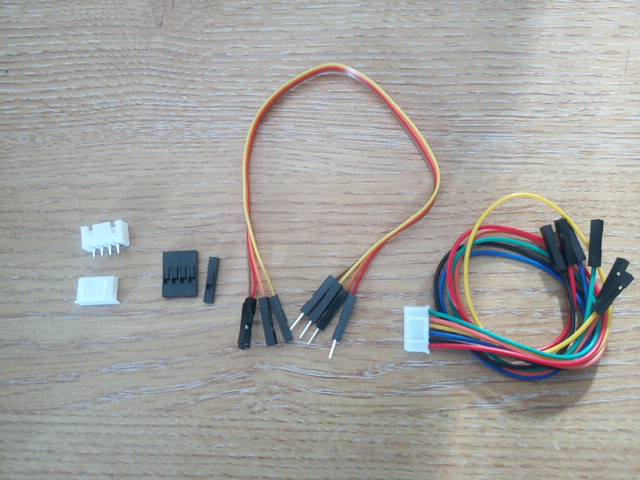
Fig 192: From left-to-right, JST-XH connectors, Dupont connector shells, Dupont cable, and Grove converter cable.
Newer microcontrollers are using miniature JST-PH fine-pitch STEMMA QT or Qwiic standard for I2C connection for 3.3v based systems. These are harder to make DIY cables for, but you can buy many varying lengths of premade cables that makes connection of I2C devices very quick and easy!
Connecting Devices
The position of the I2C pins depends on what controller module you are using:
On the Arduino Nano, the I2C pins are labelled A4 (SDA) and A5 (SCL).
On the Arduino Mega, they are pins D20 (SDA) and D21 (SCL), which are nearest to the reset button.
On the Arduino Uno, you may use pins A4 (SDA) and A5 (SCL), or pins D20 (SDA) and D21 (SCL), which are in the same place as on the Mega. Bear in mind that, even if you use pins D20 and D21 for I2C, the pins A4 and A5 cannot be used for analogue inputs.
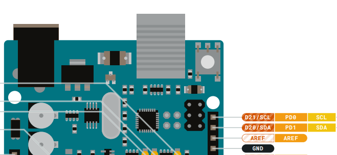
Fig 193: Arduino Mega/Uno I2C pins
Some motor shields come with header pins for the I2C connections, for example the Standard Motor Driver and the DeekRobot equivalent. The header pins are labelled, and are ringed in the images below.
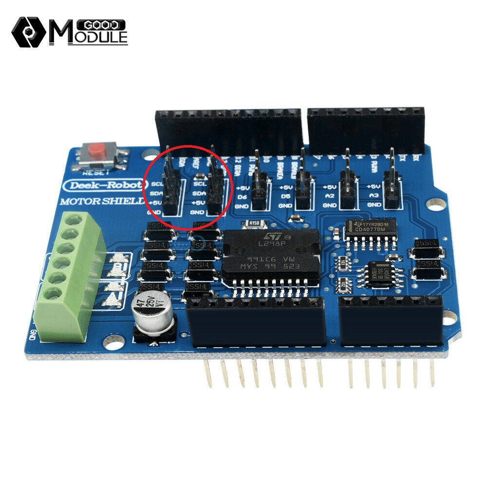
Fig 194: Motor Shield I2C pins
The next image shows an Arduino Mega and Deekrobot motor shield mounted in a 3D-printed 6-inch rack case, with one set of I2C pins connected to an OLED display on the front of the case, and one set of I2C pins connected to two external connectors at the rear of the case. The orange wires connect four LEDs (with current-limiting series resistors) that provide panel indications of incoming 5v and 14v power, and of outgoing DCC power to the Main and Programming tracks. I’ve also mounted a small self-adhesive aluminium heat sink onto the L298P device.
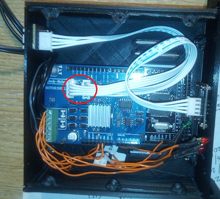
Fig 195: Motor Shield I2C pins
I2C devices are all effectively connected in parallel to the bus. If you only have one device, you can just run a four-wire connector between the pins on the Arduino, or on the Motor Shield, if you have one, to the device. Be sure to check that you connect SDA to SDA, SCL to SCL, Vcc to Vcc and GND to GND though - they are almost always in a different order on each device!
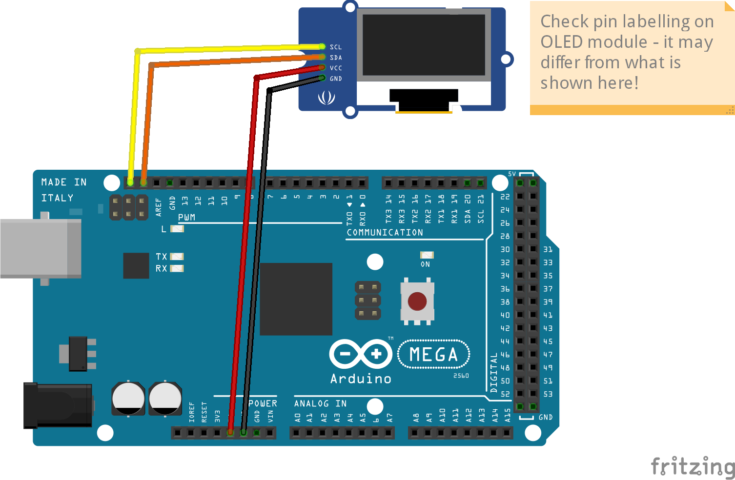
Fig 196: Connecting an OLED Display to an Arduino Mega
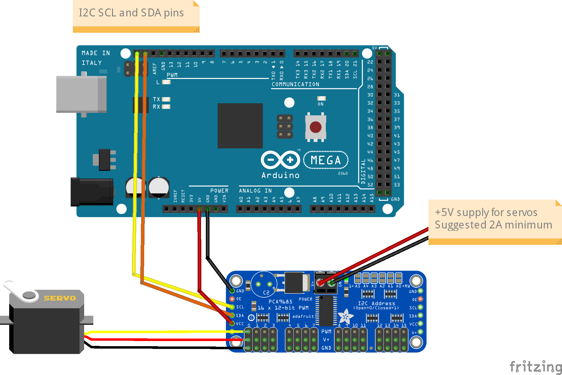
Fig 197: Connecting a PCA9685 Servo Controller to an Arduino Mega
If you have more than one device, then there are a few options open to you. Some modules (PCA9685 and PCF8574 for example) have I2C pins at both ends of the PCB, so you can use one set of pins to connect to the Arduino and the other set to connect to another device. You can chain multiple devices, subject to the restrictions described in sections for Cabling and Pull-ups.
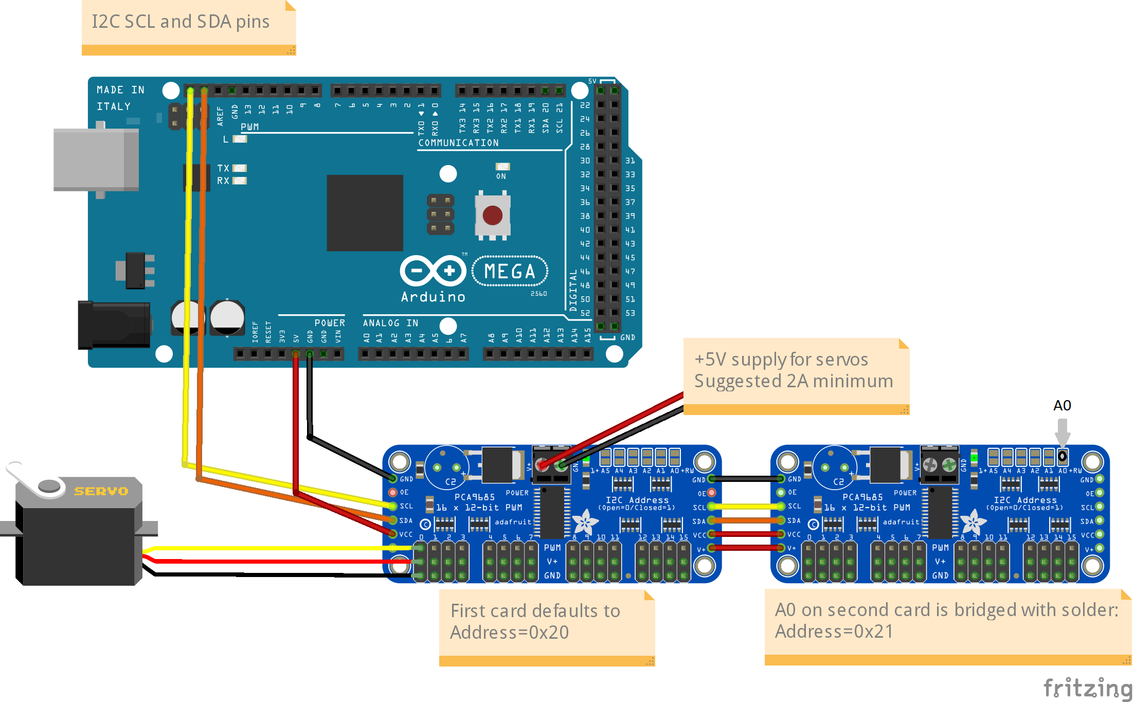
Fig 198: Connecting Two Servo Controllers
Alternatively, you can use an I2C hub, which you can purchase (SeeedStudio do one, but check that you have compatible connectors - it uses Grove connectors); or you can make one. You can use a breadboard with jumpers, or a stripboard with 4 rows of pins. Just ensure that the strips separately connect all the SCL pins together, all the SDA together, all the Vcc together and all the GND together. SeeedStudio also sell 4-wire cables with three connectors (also Grove), allowing a single connector to ‘fan out’ to two devices; by connecting another cable, you can add another device, and so on.
I use a small piece of stripboard with various 4-way pin headers and sockets soldered in, to allow various devices to be plugged in and removed as required. There is a mixture of pin headers and sockets (which accept Dupont cables) and JST-XH male sockets (which accept female cable connectors, or female Dupont connectors. I also have a four-way socket header connected in parallel, into which an OLED display is fitted for testing.
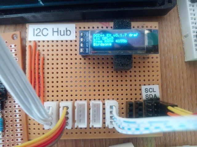
Fig 199: Home-brew I2C Hub, on Vero Stripboard (strips running left-to-right)
If you just want a temporary hookup for multiple I2C devices, then you can use a small piece of breadboard. The board shown has space for five Dupont connectors in each half row.
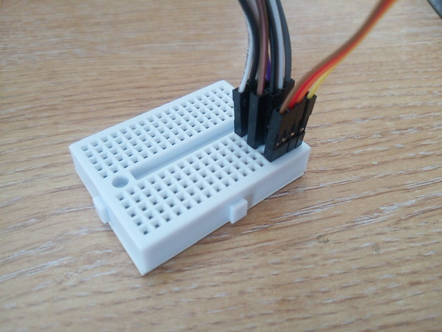
Fig 200: I2C Hub on Breadboard
Pull-ups
The I2C bus will not work unless pull-up resistors are connected to the SDA and SCL lines. However, it’s not very often that you will have to install your own pull-up resistors. Most microcontrollers have the capability to enable internal pull-ups, corresponding to around 20-50kOhm. And most I2C device modules (but not the bare |I2C| chips), contain 10kOhm pull-up resistors.
The ideal pull-up resistor value for I2C is around 1.7kOhm (at 5V, 400kHz clock), in order to be able to use long cables and high speeds. With shorter cables (<1-2m) an internal or module pull-up will generally be sufficient.
However, if you have multiple I2C modules, the pull-up resistors in them will be effectively in parallel. So two modules give an equivalent pull-up of 5kOhm, and five modules gives an equivalent pull-up of 2kOhm. With 6 or more modules, the pull-up value is, strictly, too low, and some devices, if they only just satisfy the I2C specification, may be unable to pull the bus voltage down far enough to be recognised as a LOW state. In this case, you may need to seek solutions like removing the pull-up resistors from some or all of the modules, and/or adding your own fixed pull-up. Or adding an I2C multiplexer, which will disconnect some devices from the SCL/SDA lines when they are not being actively addressed.
Removal of Pull-ups
If you want to remove the pull-ups from your modules and add your own (single) pull-up resistor to the I2C bus, then the first thing to do is identify which components on the module PCB are the pull-up resistors. Many modules have full documentation available (including circuit diagram and PCB layout), which will help to identify the pull-ups. Check the web sites for the suppliers.
As examples of where to find the pull-up resistors, take a look at the figures below:
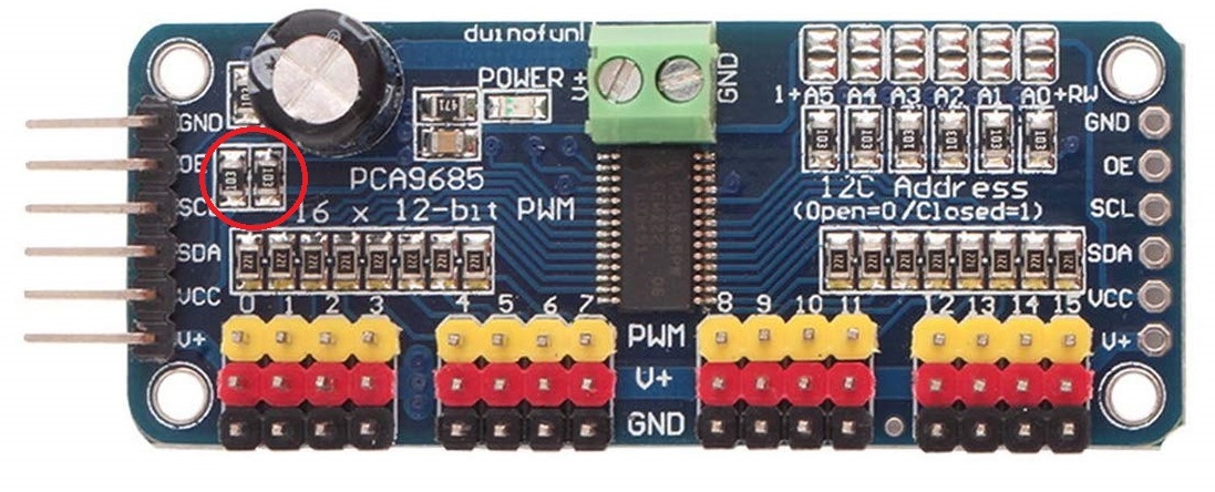
Fig 201: Location of Pull-up Resistors for PCA9685 Module (ringed in red)
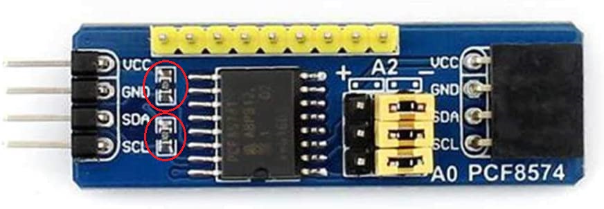
Fig 202: Location of Pull-up Resistors for PCF8574 Module (ringed in red)
Check the PCB tracks from the SDA and SCL pin connectors; one side of each resistors will be connected to one of these, and the other side of both will be connected to the Vcc supply.
Warning
IMPORTANT: When you desolder the resistors, ensure that you don’t leave any residual solder forming a connection between the two pads.
Cabling Limits
The I2C bus spec allows bus operation at various speeds - on the Arduino, speeds of 100kHz and 400kHz are generally used. Some devices are not specified to operate at the higher speed (e.g. PCF8574) although my testing hasn’t shown any problems.
The number of devices and the amount of cable on an I2C bus is limited, in the I2C specification, only by the total capacitance, which at 400kHz should be no more than 400pF. At this capacitance and the optimal pull-up value, the time taken for the bus wire to be pulled up from LOW to HIGH state is significant, compared to the pulse length. With a higher pull-up value (e.g. 10kOhm), the maximum permitted capacitance will be lower. If you need to run with higher capacitance (e.g. for longer cables), then it is possible to reduce the I2C clock speed. On EX‑CommandStation, operation will continue even with I2C speeds of 32kHz or lower, although the scan interval for digital inputs, and the refresh time for I2C displays, may be noticeably slower at speeds lower than 32kHz.
Changing the Clock speed
In EX‑CommandStation the I2C clock speed is normally the highest speed supported by all configured devices. It may however be overridden within the mySetup.h or myHal.cpp file, with a command of the form:
I2CManager.forceClock(100000);
(this sets the clock speed to 100kHz.)