![]()
WiFi Configuration


This page describes the software configuration options for using WiFi to connect your EX‑CommandStation (CS) wirelessly to JMRI or a wireless throttle like Engine Driver. For information on how to connect your hardware, go to WiFi Setup.
As mentioned in the above link, you will need the following to proceed:
A EX‑CommandStation with Motor Driver
A WiFi board (for Bluetooth configuration, see Supported Bluetooth Devices)
For a video, click Setting up WiFi.
Note

If using a separate ESP instead of a shield, this becomes tinkerer level.
Warning
Please be aware that the Espressif firmware shipped with Duinopeak ESP8266 WiFi Expansion and ESP-01 or ESP-01S devices will probably NOT work with EX‑CommandStation out of the box.
(Note: The recommended Makerfabs ESP8266 WiFi Shield is now shipping with the correct firmware version and will work with EX‑CommandStation without modification).
This can be corrected, but is probably beyond Conductor level and requires additional hardware.
See ESP8266 (WiFi Boards) - AT Version Issues and Solutions for details on how to check the version and how to correct it if needed.
Wireless Connections
As mentioned in WiFi Setup, there are two main reasons for wanting to use WiFi; to connect to JMRI without a USB cable, or to connect to a wireless throttle (controller) like the Engine Driver mobile app. While it can work to simply use WiFi to replace the USB cable to connect the computer running JMRI to your Command Station, there are better ways and frankly, your electronics are usually under the benchwork, so just buy the right sized cable.
But if you have no alternative and need to replace the cable with wireless, we recommend the HC-12 serial wireless bridge boards which we cover on the HC-12 Wireless Bridge page.
That said, there are two main wireless technologies that let you send commands to your Command Station and control your trains:
WiFi
Bluetooth
Your particular controller hardware (a separate controller or your cell phone) may be able to use either or both depending on the controller you choose. This tutorial covers WiFi configuration, for Bluetooth see Supported Bluetooth Devices.
Connection Type: Direct to Command Station or through JMRI
Everything on this page seems to come in twos! You have two options for connecting your throttle (controller) to your Command Station depending on its capabilities and your preferences:
Connect directly to EX‑CommandStation using WiFi or Bluetooth (JMRI not required but optional)
Connect to the EX‑CommandStation through JMRI with the USB cable, and connect a wiThrottle Protocol compatible throttle to JMRI’s wiThrottle Server via WiFi
If you don’t need JMRI, or just want to connect your wireless throttle (controller) directly to the EX‑CommandStation, then you connect to the Command Station using a WiFi or Bluetooth device that speaks either the DCC-EX Native Commands, or the wiThrottle Protocol command language.
For example, Engine Driver uses the wiThrottle Protocol, so it can connect either directly to the EX‑CommandStation via WiFi, or indirectly through the JMRI computer that has WiFi and its own wiThrottle Server. DCCpp CAB can connect directly to the EX‑CommandStation via WiFi or Bluetooth, and sends DCC-EX Native Commands.
What’s a “WiThrottle Server”?
wiThrottle stands for “WiFi Throttle”, and a “wiThrottle Server” is just software running on your JMRI computer or on the EX‑CommandStation that communicates using the wiThrottle Protocol. It’s called a “Server” because it allows you to connect to it and it “serves”, or services, requests from another application. That application is called a “Client”. So your throttle in this case is the client.
wiThrottle Protocol itself is a standard for how WiFi throttles can communicate with Command Stations, much like the DCC standard is a standard for how data packets communicate with decoders. What this means for you, is that any device that is wiThrottle Protocol compatible should work with the EX‑CommandStation. Also, any device that sends DCC-EX Native Commands should work with EX‑CommandStation.
Access Point Mode vs. Station Mode
There are two ways to configure the WiFi board connected to EX‑CommandStation: “Access Point Mode” (aka “AP MODE”), and “Station Mode”. We often abbreviate the latter to “STA”. You will also see people refer to it as “Client Mode”.
Access Point Mode
In Access Point (AP) (AP) mode, the tiny ESP-WiFi chip acts as a very basic WiFi server and provides a small IP network for your throttle or for your computer running JMRI with the wiThrottle Server enabled. It acts much like your router does to let things connect directly to it (currently up to four connections).
Using the Command Station in Access Point (AP) mode allows you to have a separate network so you can keep your layout network separate from your home network. This is the simplest way to enable a connection for a WiFi throttle.
If you travel to shows, or take your setup to a friend’s house, this allows for an autonomous, transportable system that does not need a connection to, and hopefully will not interfere with, other networks.
Note
In this mode there is no connection to the Internet for any of the devices that are only connected to the AP. It simply provides a private network to allow a direct connection to your throttles (controller).
(Remember you can click on images to enlarge them)
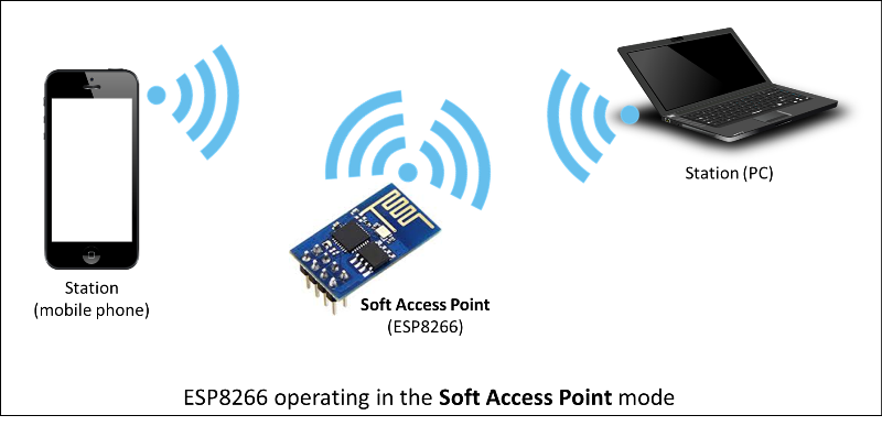
Fig 178: Access Point Mode - Things connect to the WiFi Board
Station Mode
Station (STA) Mode allows you to connect the Command Station to your existing home network. The Command Station becomes a Station or Client rather than an Access Point (AP). That means instead of being a host that manages the IP of the smartphone that runs your Throttle, it becomes a station that connects to your existing network just like any of the other computers or devices connected to your network.
The Throttle then connects to the Command Station by finding its IP address on the network. You will have to find what IP address is assigned to the Command Station (see below). Alternately, you can define a static IP address in your router to assign to the Command Station.
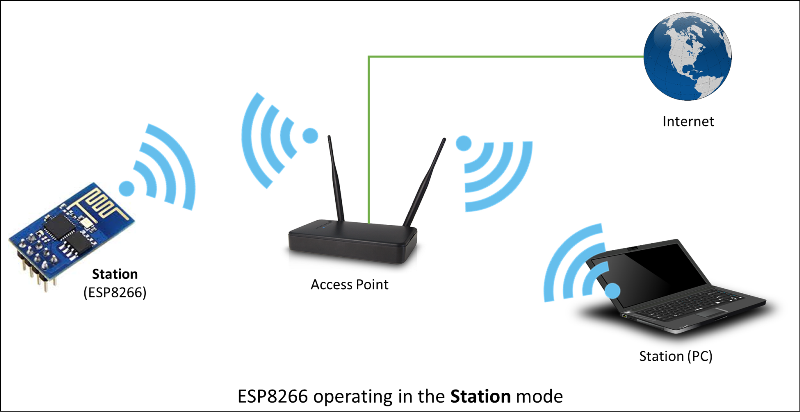
Fig 179: Station Mode - Things connect to the router and find the WiFi board by its IP address
Images are courtesy of NodeMCU. You can find a great tutorial on WiFi there also.
We will focus on how to connect a Throttle to the Command Station. For info on using WiFi with JMRI, refer to the JMRI documentation  .
.
Access Point Mode (Default - No Configuration Necessary)
To use the default Access Point (AP) Mode, you don’t have to do anything other than connect an ESP8266 board as described in WiFi Setup.
That’s it! If there is no previously configured network in range, or the WiFi setup in your config.h file is still unconfigured, the default for EX‑CommandStation is Access Point (AP) mode. We find your WiFi board, no matter which of the extra serial ports you attached it to. EX‑CommandStation then accepts commands from WiFi throttles in either wiThrottle Protocol or DCC-EX Native Commands.
To see other configuration options you can set in your config.h file, see WiFi Config Options below.
You will need to know:
The IP address assigned by the WiFi board (Usually 192.168.4.1)
The port to communicate through (port 2560 unless you change it in your config.h file)
The SSID or Server name to connect to (DCCEX_xxxxxx where the x’s are the last 6 digits of your device’ MAC address)
The password (Unless you change it in config.h, your local WiFi password.) Its default is PASS_xxxxxx where the x’s are the last 6 digits of your device’ MAC address)
Note
All of this information is displayed in the startup log if you connect the Command Station to a Serial Monitor. The IP address and port also appear on the optional LCD or OLED display.
If you wish to use a custom SSID in access point mode, you will need to set the WIFI_FORCE_AP option in config.h, see #define WIFI_FORCE_AP
Whenever you connect a USB cable and open the Serial Monitor, you reset the program running on your Command Station. It will go through the bootup sequence again and try to connect to a network. If you did not setup a “Station Mode” configuration, or if that network is not in range, it will configure itself in Access Point (AP) mode. You will see this process by watching the Serial Monitor log window.
Here are the important lines you need to look for. While the IP address is almost always 192.168.4.1, it could be different on your system. You are looking for the items in the blue box below that are highlighted in red.
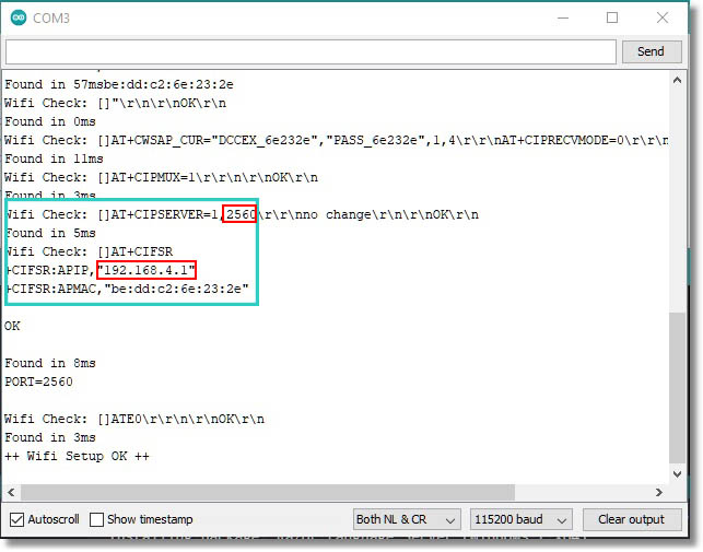
Fig 180: Serial Monitor Log (click to enlarge)
You will see the line that has AT+CIPSERVER=1,2560\r\r\nno change\r\n\r\nOK\r\n, where 2560 is your port number
Next you will see +CIFSR:APIP,"192.168.4.1", where your IP address is 192.168.4.1.
APIP here stands for “Access Point IP Address”. Your throttle is assigned an IP address in the same IP range, typically 192.168.4.10 to 15. As your Access Point (AP) is also your EX‑CommandStation this time, you connect your throttle to the Access Point (AP) IP.
Tip
Remember to enter IP xxx.xxx.x.xx and port xxxx numbers correctly into your WiFi Throttle when you configure that later.
You will also see your SSID and Password in the log.
Once you see an Access Point (AP) IP Address and see ++ Wifi Setup OK ++ at the bottom of the log (it may take a few seconds for the Command Station to complete the configuration), you can connect to it!
Connecting to the Access Point
There are two steps to get you running trains with your WiFi throttle.
Connect your phone’s WiFi to the Command Station Access Point (AP) instead of your home network.
Connect your throttle app to the Command Station Access Point (AP) in its settings.
On your mobile device, go into your WiFi settings the same way you would to connect to your home router. Look for another network name to connect to.
You should see a new network that begins with “DCCEX” like this example: DCCEX_6e321b. Remember those last 6 digits; this is the MAC address to be used later.
Simply click on that network and connect to it on your mobile device. You will need to enter the password you specified in the config.h file. If you did not enter one, the default will be PASS_xxxxxx where “xxxxxx” are the same last 6 digits of your device’s MAC address displayed in the SSID like this example: PASS_6e321b
Note
The last 6 letters and numbers of your Access Point (AP) name and default password will be specific to your WiFi board, and uniquely identify it. They are the last 6 letters of that device’s MAC address. You can always find it in the log or by simply looking at the DCCEX_xxxxxx SSID name in your list of available networks.
Ignore the warning that may pop up telling you that “Internet may not be available”. The Command Station is not connected to the internet, and you are connecting to the Command Station directly from your mobile device for the purpose of controlling trains, not surfing the web. Depending on the config and OS of your mobile device, you may still have internet access over mobile data through a cell tower connection.
If you wish to use your home network internet (for example, if your data plan is expensive), turn off mobile data and see the section below on Station Mode to connect using your home network instead.
Once you are connected to the Command Station with your cell phone, you can run your WiFi Throttle app, enter the IP Address for the Server Address (the default is usually 192.168.4.1, but it will be displayed in your serial monitor log if you are unsure), enter 2560 for the port number, and then select and acquire your loco by its address. If you don’t know your loco address, see the <R> command in the <R> - Read DCC decoder (cab) address section of the Command Reference.
Note
Your Mobile Throttle function keys are user defined default function keys, not the function keys you used in either JMRI or Rocrail engine roster function keys.
Once again:
IP Address - Normally 192.168.4.1
Port Number - 2560
Server Name - DCCEX_123456 where the last 6 characters are unique to your WiFi device
Server Password - PASS_123456 where the last 6 characters are the same as above
All this information appears in the startup log when connected using a serial monitor, in case you forget.
Note
If you experience dropped connections to the AP, turn off the Auto-connect feature on your phone to prevent it from randomly disconnecting from the Access Point (AP) and connecting to your home router because it thinks it’s a better connection. You can also “Forget” the connection it wants to switch to and then manually connect to that network when you need it.
Connecting to your Network - Station Mode “STA” (edit config.h)
Important
While it is possible change your network settings using the Arduino IDE, we seriously DO NOT RECOMMEND IT for a Conductor or Tinkerer. It is an order of magnitude more complex, much slower, and with a very high probability of getting something wrong unless you really know what you are doing.
Just run EX‑Installer and select your required WiFi settings.
In order to connect to your home network, you must open the config.h file and enter your login credentials, unless you have already entered your credentials earlier via the automated EX‑Installer.
This can be done in a Text Editor. The other way to do this, other than the recommended way using EX‑Installer, is to use the Arduino IDE and open the project.
Look for these lines in the file:
/////////////////////////////////////////////////////////////////////////////////////
//
// NOTE: Only supported on Arduino Mega
// Set to false if you do not want it even on the Arduino Mega
//
#define ENABLE_WIFI true

/////////////////////////////////////////////////////////////////////////////////////
//
// DEFINE WiFi Parameters (only in effect if WIFI is on)
//
#define WIFI_SSID "Your network name"
#define WIFI_PASSWORD "Your network passwd"
#define WIFI_HOSTNAME "dccex"
First, make sure that the #define ENABLE_WIFI true line is not commented out. Two slashes // in front of a line make it a comment, and not a line of code.
Next, enter your network information into the WIFI_SSID, WIFI_PASSWORD and WIFI_HOSTNAME fields. Here is an example:
#define WIFI_SSID "JonesFamily"
#define WIFI_PASSWORD "Secret!2020"
We recommend leaving WIFI_HOSTNAME to “dccex”, but you can change it if you like. If your ESP8266 WiFi board has a later version of firmware, that can allow you to connect using this name instead of the IP address. In other words, it allows that name to be an alias for the IP address.
Save your config.h file and upload the sketch to your Command Station.
WiFi Config Options
The following defines are all the possible network settings found the config.h file. If you used the automated installer, you may see a few of these already listed. If you do a manual Arduino IDE install, you will see all of these in the file you renamed from “config.example.h” to “config.h”.
#define IP_PORT 2560
Default: 2560 - This is the port used to communicate with the WiFi board or Ethernet Shield.
You can change this value if you would prefer it to be something else. However, you will need to enter this in software like Engine Driver in order to connect to the Command Station via networking as Engine Driver will not be able to ‘guess’ it.
#define ENABLE_WIFI true
Default: true - WiFi is supported only on a Mega. If you do not wish to use WiFi, and want to save boot time by not having the Mega check for a WiFi board each time, you may set this to “false”.
#define DONT_TOUCH_WIFI_CONF
Default: commented out If uncommented, this tells the Command Station to NOT process any WiFi commands in the Command Station. If other WiFi defines are enabled, the Command Station will ignore them. With this command, you can leave #define ENABLE_WIFI true so that networking is active, but send no configuration commands to ESP8266.
This allows you to enter your own AT commands to set up your WiFi however you want. To do this, you would enter <+> commands in the Serial Monitor, or add code to send these commands automatically.
#define WIFI_SSID “Your network name”
Default: “Your network name” - To connect to your Command Station as an Access Point (AP), do not change this setting. If you wish to connect to your home network instead, enter the SSID (network name) for that network.
If you do NOT set the WIFI_SSID, the WiFi chip will first try to connect to the previously configured network, and if that fails, fall back to Access Point mode. The SSID of the Access Point (AP) will be automatically set to DCCEX_xxxxxx, where xxxxxx is the last 6 digits of the MAC address for the WiFi chip.
Your SSID must not contain " (double quote, ASCII 0x22).
#define WIFI_PASSWORD “Your network passwd”
Default: “Your network passwd” - WIFI_PASSWORD is the network password for your home network, or if you want to change the password from default Access Point (AP) mode password to the Access Point (AP) password you want. Your password must not contain " (double quote, ASCII 0x22).
If you don’t change this setting and start up in Access Point (AP) mode instead, the default password is PASS_xxxxxx where xxxxxx is the last 6 digits of the MAX address for your ESP board.
#define WIFI_HOSTNAME “dccex”
Default: “dccex” You would normally not want to change this, as it is the host name that will appear in the list of available networks displayed for devices connecting to DCC-EX. It helps you know which WiFi device is your Command Station.
#define WIFI_CONNECT_TIMEOUT 14000
Default: 14000 milliseconds (14 seconds) - You only need to set this if you have an extremely slow WiFi router, and the response to the connection request takes longer than normal.
#define WIFI_FORCE_AP
New in version 5.4
Default: commented out - Uncomment this line if you wish to use a custom SSID for your WiFi in access point mode, otherwise defining a custom SSID will cause the WiFi to attempt to connect to an existing WiFi network is STA mode.
#define ENABLE_ETHERNET true
Default: commented out - Uncomment this line if you wish to use an Ethernet Shield & cable (not WiFi, see above for that). You will also need to install the Arduino Ethernet Library on whichever IDE you use to compile and upload your sketch.
#define IP_ADDRESS { 192, 168, 1, 200 }
Default: commented out - Uncomment this line if you wish to use a static IP address, otherwise the Command Station will use DHCP to automatically assign an IP address from your router. If you use a static IP, you will also have to configure this IP in your router.
Note - this is only valid when using Ethernet, and does not apply to WiFi.
#define MAC_ADDRESS { 0xDE, 0xAD, 0xBE, 0xEF, 0xFE, 0xEF }
Default: commented out - This is for Ethernet only! Ethernet shields do not normally come with a defined MAC address. We give you two, and you can uncomment the one you prefer. You can also choose any other validly formatted MAC address that will not conflict with any devices already on your network.
Resetting Network Settings
Once you enter a network SSID and password, the Command Station will always try to connect to it, even after removing the power and restarting. If you want to connect in Access Point (AP) mode, or your network credentials change, or you need to connect to a different network, you simply need to tell your WiFi board to clear the settings.
Clearing the ESP-WiFi SSID Settings
Open your Serial Monitor and wait until the Command Station has gone through the startup sequence. Then in the command textbox enter <+RESTORE> and press “SEND”.
You will then see an “Ok” message. The WiFi Settings are forgotten. However, if the last config.h used when you uploaded it to the Command Station had WiFi credentials in it, then as soon as your Command Station restarts, it will load and save those settings again. So…
If you want to run in Access Point (AP) mode
Edit the config.h, change your SSID and password lines back to default. It MUST look like the following. If it is anything else it will try to login with whatever you type there as credentials!
#define WIFI_SSID "Your network name"
#define WIFI_PASSWORD "Your network passwd"
Then upload the project into the Command Station.
If you want to change your network login
Edit the config.h file, change your SSID and password to your new credentials, and then upload the project into the Command Station.
Disabling WiFi
Edit the config.h file. Comment out the line #define WIFI_ENABLE true by adding two forward slash marks (//) in front of the line. Then upload the project back to the Command Station.
Network Startup sequence
For reference, it may be helpful to know the sequence the Command Station uses to try and establish a network connection. The following provides the flow of this sequence.
Check for a WiFi Device - Scan serial ports 1, 2, and 3 in order to look for WiFi. If no response, abort network setup and start the Command Station without WiFi.
If we find a WiFi device, next check if
#define DONT_TOUCH_WIFI_CONFis uncommented. If so, abort config attempts here - done.Next, if no SSID is configured, check if the ESP is configured in STATION mode already from a previous network connection. If so, try to connect to that network. If we connect, exit and start the Command Station, if not, go to step 4.
Try to configure in STATION mode from values in the config.h file - done.
If none of the above, set up as an Access Point (AP) with an SSID of DCCEX_xxxxxx and a password set in the config.h file. If unconfigured, the default will be PASS_xxxxxx (xxxxxx will be the last 6 characters of the device SSID & MAC address)
Tips and Tricks
There are circumstances where you may want to make temporary changes to your network, such as when you take your layout to a show. The following are some handy things you can do.
Remember…
Use a Serial Monitor connected to the USB port of your Command Station, and enter the commands you need.
If you disconnect the Serial Monitor and reconnect it (or anything else) to the USB port, it will reset the Command Station, and it will go back to the default configuration.
Press “send” after each command.
Temporarily Log Into A Different Network
Forget your network settings by entering
<+CWQAP>in the Serial Monitor.Login to the new network by entering either a new local SSID & password, or using the Command Station in Access Point Mode.
Create a Static IP for your Command Station in Access Point Mode
You are still going to have to go into your router, find the MAC address for your WiFi board (or find it in the Serial Monitor log) and then assign a static IP address (sometimes called “reserved” IP address) to that MAC. That should be all you need, as the DHCP server on your network will assign that IP to your Command Station when the Command Station asks for one.
You can try these commands also. You must have a recent version of the firmware to support _DEF commands. If they don’t work, try entering them without this suffix (Example: <+CIPAP> instead of <+CIPAP_DEF>)
Forget your network settings by entering <+RESTORE>
Enter
<+CIPAP_DEF="192.168.5.1","192.168.5.1","255.255.255.0">to setup the Access Point (AP) with your IP addressEnter
<+CWDHCP_DEF=1,1>Enter
<+CWDHCPPS_DEF="1,10,"192.168.5.100","192.168.5.150">