Solenoid or coil turnouts/points


Important considerations for solenoid/coil turnouts/points
Solenoid/coil based turnouts are switched by very small coils that are typically designed to be energised for very brief periods of time (read milliseconds, not seconds), and leaving these energised for too long will burn them out.
If not using the manufacturer’s turnout/point control hardware, the safest option is to use a capacitive discharge unit (CDU), as the short duration discharge of the capacitor is what is used to energise the coil.
If switching the points digitally via some other means such as a motor driver IC or relay, use the shortest duration that provides reliable switching.
Defining solenoid/coil based turnout objects
To define solenoid/coil based turnouts directly in your EX‑CommandStation via the serial console, use the appropriate one of these commands:
<T id VPIN vpin>- use this command when using a turnout/point controller that uses a single pin, whether connected directly to your EX‑CommandStation or via an I/O expander device<T id DCC linear_address>- use this command when using DCC accessory decoders to control the turnout/point
Refer to Turnouts/Points (Configuring the EX-CommandStation) for details on these commands.
To define solenoid/coil based turnouts using EXRAIL (whether or not they are to be automated) via the “myAutomation.h” file, use the appropriate one of these commands:
PIN_TURNOUT(id, vpin [, "description"])- use this command when using a turnout/point controller that uses a single pin, whether connected directly to your EX‑CommandStation or via an I/O expander deviceVIRTUAL_TURNOUT(id [, "description"])- use this command when you need to define a custom macro that controls the various pins and duration required to switch a turnoutTURNOUT(id, addr, sub_addr [, "description"])- use this command when using DCC accessory decoders to control the servos
Refer to Turnout/Point Objects - Definition and Control for details on these commands, along with Adding Turnouts/Points for some further information and examples.
Connecting and controlling the hardware
Using an L293D motor driver - single solenoid/coil turnouts
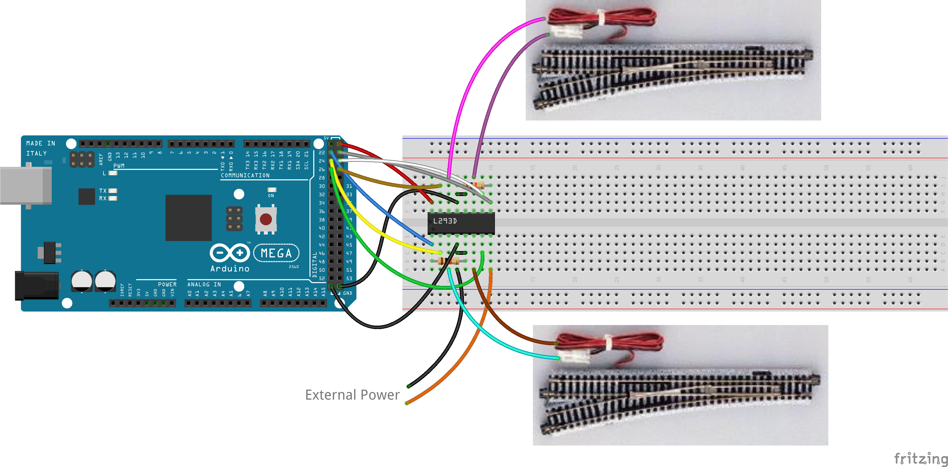
A single L293D motor driver IC can be used to control two turnouts/points and will require six digital output pins either directly from your EX‑CommandStation (as per the diagram above), or these can also be connected via an I/O expander such as an MCP23017 or EX‑IOExpander.
To operate the turnouts/points in this manner, the direction of the turnout (close/throw) is configured by setting the input pins (2 and 7, 10 and 15) high or low, and briefly setting the appropriate enable pin high (1 or 9).
Note that the 10K pull down resistors connected from ground to the enable pins are there as a safety feature to ensure that any unknown states during start up don’t cause the enable pins to be set to a high state, causing the coils to overheat and burn out.
The voltage provided to “External Power” is the voltage required to operate the turnouts/points, and will depend on the brand/model. Absolute maximum for the L293D is 36V DC.
Here is an example EXRAIL macro that will configure a virtual turnout, setting the correct pins for the two turnouts to operate correctly:
#define PULSE 10    // Set the duration of the pulse to 10ms
#define SINGLE_COIL_TURNOUT(t, p1, p2, p3, desc) \
VIRTUAL_TURNOUT(t, desc) \
DONE \
ONCLOSE(t) \
 SET(p2) RESET(p3) \
 SET(p1) DELAY(PULSE) RESET(p1) \
DONE \
ONTHROW(t) \
 RESET(p2) SET(p3) \
 SET(p1) DELAY(PULSE) RESET(p1) \
DONE

SINGLE_COIL_TURNOUT(101, 22, 24, 26, "Turnout 101")
SINGLE_COIL_TURNOUT(102, 23, 25, 27, "Turnout 102")
Before implementing this macro (or any similar macro controlling solenoid/coil turnouts/points), it is imperative that the correct voltage for the brand and model of turnouts/points is known, and that the defined pulse or delay time is kept to the minimum value possible for reliable switching of the turnouts/points.
Using an L293D motor driver - dual solenoid/coil turnouts
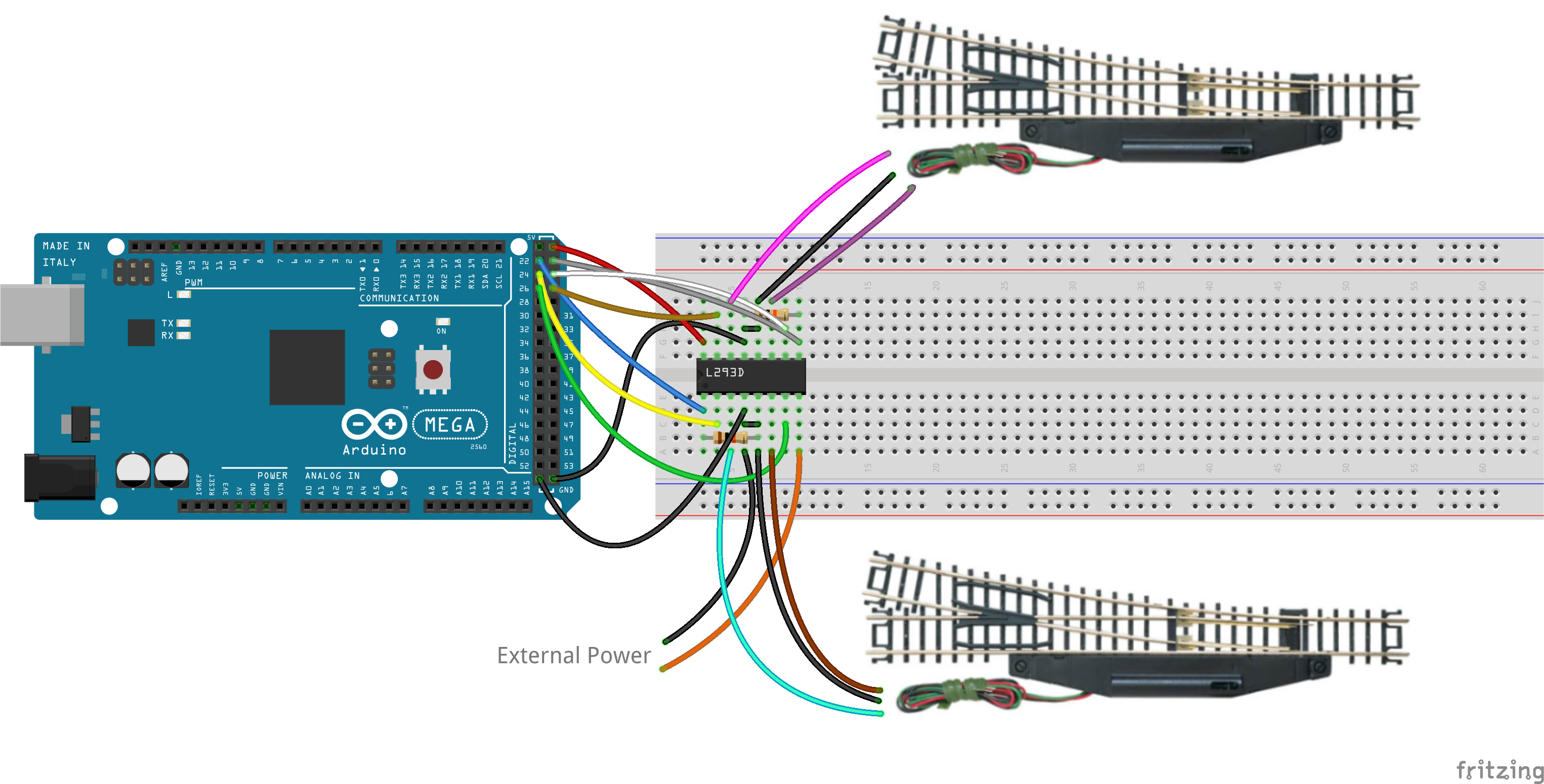
Like the single solenoid/coil turnouts, a single L293D motor driver IC can be used to control two turnouts/points. This will still require six digital output pins either directly from your EX‑CommandStation (as per the diagram above), or these can also be connected via an I/O expander such as an MCP23017 or EX‑IOExpander.
To operate the turnouts/points in this manner, the direction of the turnout (close/throw) is still configured by setting the input pins (2 and 7, 10 and 15) high or low, and briefly setting the appropriate enable pin high (1 or 9). The key difference for dual solenoid/coil turnouts is the common (third) wire of the turnout being connected to ground as per the diagram above.
Note that the 10K pull down resistors connected from ground to the enable pins are there as a safety feature to ensure that any unknown states during start up don’t cause the enable pins to be set to a high state, causing the coils to overheat and burn out.
The voltage provided to “External Power” is the voltage required to operate the turnouts/points, and will depend on the brand/model. Absolute maximum for the L293D is 36V DC.
Here is an example EXRAIL macro that will configure a virtual turnout, setting the correct pins for the two turnouts to operate correctly (note it is identical to the single coil version, but renamed):
#define PULSE 10    // Set the duration of the pulse to 10ms
#define DUAL_COIL_TURNOUT(t, p1, p2, p3, desc) \
VIRTUAL_TURNOUT(t, desc) \
DONE \
ONCLOSE(t) \
 SET(p2) RESET(p3) \
 SET(p1) DELAY(PULSE) RESET(p1) \
DONE \
 ONTHROW(t) \
 RESET(p2) SET(p3) \
 SET(p1) DELAY(PULSE) RESET(p1) \
DONE

DUAL_COIL_TURNOUT(101, 22, 24, 26, "Turnout 101")
DUAL_COIL_TURNOUT(102, 23, 25, 27, "Turnout 102")
Before implementing this macro (or any similar macro controlling solenoid/coil turnouts/points), it is imperative that the correct voltage for the brand and model of turnouts/points is known, and that the defined pulse or delay time is kept to the minimum value possible for reliable switching of the turnouts/points.
Using a Capacitive Discharge Unit (CDU) - single solenoid/coil turnouts
Todo
MEDIUM - Add CDU info
Using a Capacitive Discharge Unit (CDU) - dual solenoid/coil turnouts
Option 1 - DIY CDU by “Rosscoe” (DCC-EX user on Discord)
The information here is based on the combined driver and CDU as outlined in this GitHub repository, with a PCB available from PCBWay 
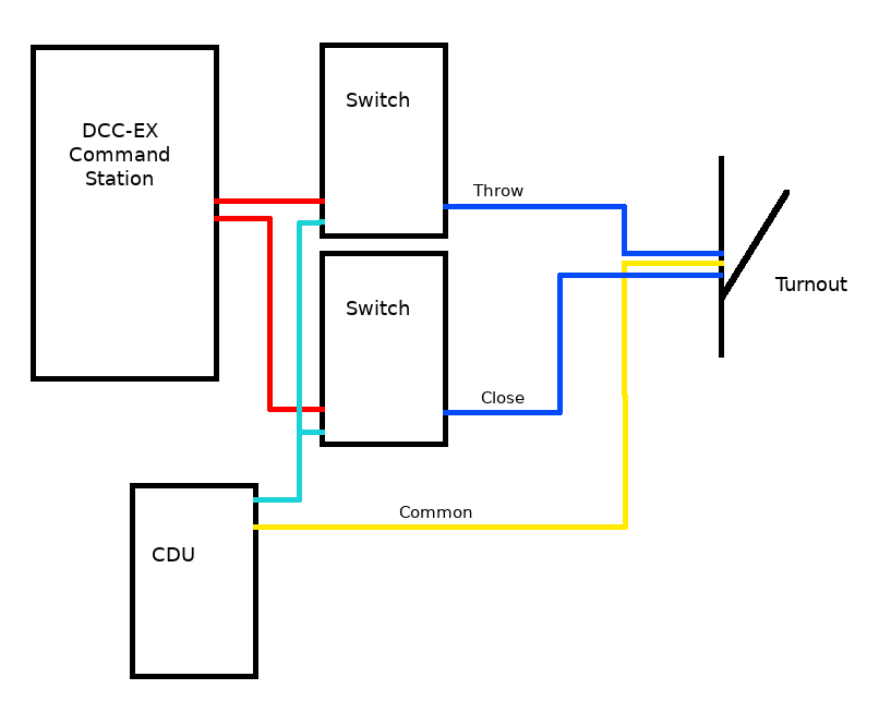
This board has an MCP23017 which is connected to your EX‑CommandStation via I2C, which is then controlled like any other MCP23017. This MCP23017 controls two ULN2803 darlington arrays to switch power to the turnout/point solenoids.
The connections will depend on the driver and CDU.
On the turnout/point solenoids, there will be three wires: a common wire, a wire to close the turnout, and a wire to throw the turnout.
With the above driver board, the common is positive and the control wires are connected to ground by the darlington drivers.
The EXRAIL macro below creates a turnout object that closes/throws the turnout/point via the MCP23017 vpins on the board.
The DUAL_SOLENOID_TURNOUT definition is:
id - turnout id
pc - pin for CLOSE command
pt - pin for THROW command
desc - description
ali - alias that can be used for the turnout in EXRAIL
#define PULSE 10 //10 mSec
#define DUAL_SOLENOID_TURNOUT(id,pc,pt,desc,ali) \
VIRTUAL_TURNOUT(id,desc) \
ALIAS(ali,id) \
DONE \
ONCLOSE(id) \
 SET(pc) \
 DELAY(PULSE) \
 RESET(pc) \
DONE \
ONTHROW(id) \
 SET(pt) \
 DELAY(PULSE) \
 RESET(pt) \
DONE

// Example use of this macro using first two pins on the first MCP23017 I/O expander
DUAL_SOLENOID_TURNOUT(1,164,165,"Example CDU turnout",EXAMPLE_TURNOUT)
Notes on Some Specific Hardware
Connecting A Tortoise
A Tortoise is still a solenoid turnout/point motor that need a voltage applied for a certain amount of time and to reverse polarity to go in the other direction. They implement it as a stall motor, which means if you were willing to waste 15-20mA of current at idle, you can use a switch and it just stalls out at the end of travel. But now we get into the weeds about all the different ways you can control your Tortoise. The issue is that a command station can’t directly control things that require a lot of current or voltages higher than 5V or on the CSB1 3.3V. So we control a switch of some kind, like a relay or transistor, that CAN handle that load.
The easiest solution costs you $60 from Jack Reagan at Smart Hobby LLC which buys you a 16 output capacitive discharge board. You connect it to the I2C port on the CSB1, then a simple EXRAIL script he supplies goes in your myAutomation.h file and you are done. The turnouts/points would appear on an Engine Driver or JMRI and you just THROW and CLOSE them.
You can add sensors and have the turnouts/points controlled by the route you want your trains to follow. Benefit here is that the Smart Hobby CS board can also control snap switches like Kato and any other single or dual coil switch machine that needs a strong, short, burst of energy. Jack also supports you so you can ask him the questions.
Rosscoetrain has a similar board and an accessory controller version. You define a DCC_TURNOUT and his controller does the rest since it acts like an 8 port DCC accessory decoder. It takes a DCC turnout command from the track. It also can control anything else that needs on/off power control such as LED lighting, motors, etc. Rosscoetrain also provides support.
A simple but less easy method is to use a DPDT relay and a MCP23017 port expander board (dirt cheap and also connects to the I2C port) or our EX‑IOExpander software running on a cheap processor like an Uno or Nano or Elegoo Mega. Define each turnout as a PIN_TURNOUT. This wastes 15-20mA or more of current for each one all the time since the power never gets shutoff. The way around that is to use a motor driver board to act as a solid state relay. Transistors on the board and an EXRAIL script control both the polarity switching and the duration of the voltage. We have those simple scripts, so you don’t need to know C++ or electronics to throw a turnout/point. People have used all sorts of inexpensive boards for this, including Rosscoetrain’s motor board which has 4 MOSFET transistors.
Regardless of which method you use, take a look at the documentation for EX‑IOExpander since it has a lot built into it. And you can connect the Smart Hobby board and a lot of other things to it.