![]()
I2C Displays


EX‑CommandStation supports both LCD and OLED to display status and other user-defined information. While a command station is typically hidden away under a layout, if you like the idea of a nice visual display for your panel, several different I2C displays will work. You can use either a 20 character by 2 line or 4 line LCD display, or an OLED display capable of up to 8 lines.
EX‑CommandStation can support more than one display and indeed write to them from within EXRAIL for fancy lineside or auxilliary displays.
Further to this, the new EX‑Installer can now configure the main status display during installation making adding a display very simple. The command station code is also easily configurable in order to add more displays, change the display settings, as well as add or change what is printed on the display.
We currently support various displays:
LCDs based on the PCF8574 backpack with 16 column by 2 row (16x2) and 20 column by 4 row (20x4) displays attached
OLED displays in .96” and 1.3” formats based on SSD1306 and SH1106 display controllers
Note
Do NOT modify any code related to displays without contacting us. We use our own included code, NOT an external library you have to download. The code was written to support LCD and OLED displays and to fit on a Mega and an Uno. It has a custom font table and the LCD macro works to output diagnostics even if there is no display. If your display is not supported, let us know and we can take a look.
The LCD displays require a “backpack” that converts the raw display to I2C. I2C allows us to use just 2 lines (SDA (serial data) and clock (SCL)) to send text to the display. Without this board, we wouldn’t have enough pins, especially on an Uno, to use a display. The OLED displays natively support I2C and can be wired directly.
Warning
You MUST make sure to order TWO (2) parts for your LCD Displays. You need the display AND a backpack based on the PCF8574 controller chip. Some displays come with this already soldered together. Also note that some OLED displays use the SPI standard or are configured for it, so make sure to buy the I2C enabled ones, or ones that can be configured for I2C use. Make sure to check before you buy!
Examples of compatible displays
Here is an example of a 20 x 4 LCD screen. They come in different colours like blue and green. The controller board (backpack) is shown before soldering it to the back of the display. Soldering is very simple since you just match the two boards together and quickly solder the pins. Though there are 16 of them.
20 x 4 LCD with backpack
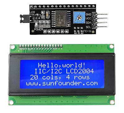
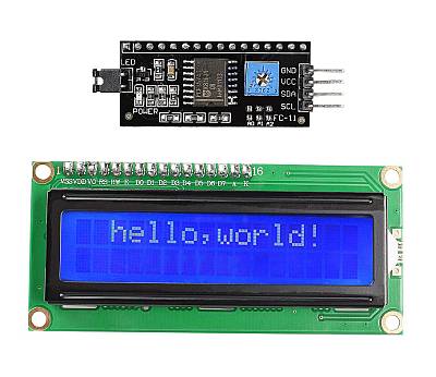
On the left is 20x4 LCD with backpack, and on the right is a 16x2 LCD.
Remember to either order an LCD display with the backpack already soldered or two order both pieces from your vendor and solder it yourself (see below.)
Some examples of supported OLED displays:
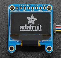
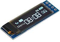
Adafruit 0.96” 128x64 OLED, and Makerfocus 128x32 .91” OLED.
Connecting an LCD Display
Warning
I2C displays come in all shapes and sizes, and often have variations in design and pinouts between different vendors and manufacturers. Be sure to check the correct orientation of pins and connectors prior to connecting your display, we cannot cover every possible scenario of connection available. Just because two displays look identical at a quick glance, they may not be.
Soldering on the Backpack (if you purchased separate pieces)
And here is a picture of the board after soldering or if you purchase a board already soldered (or “welded” as some of the Chinese sites call it)
LCD with backpack soldered to the back
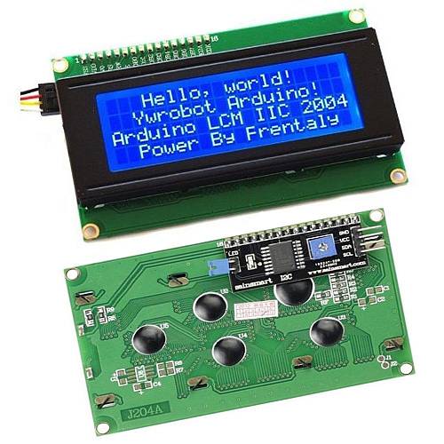
Fig 203: Backpack Soldered to LCD
Connecting the Jumper Wires
To connect the Display to the Command Station, you will need 4 male to female jumper wires:
Connect a wire from +5V on the Motor Shield or WiFi Board to Vcc on the backpack
Connect a wire from Gnd on the Command Station to Gnd on the backpack
Connect SDA on the Arduino (pin 20 on the Mega, pin 16 on the Uno) to SDA on the backpack
Connect SCL on the Arduino (pin 21 on the Mega, pin 17 on the Uno) to SCL on the backpack
Note
Look closely on the Uno or Mega for markings, including on the inside or outside of the black header. SCA and SCL are usually clearly labelled.
Connecting an OLED display
OLED displays come in more varieties than LCD displays. The library to run them also takes more memory. Therefore, OLED displays won’t work with an UNO and you will require a Mega. Here are some examples of OLED displays:
Adafruit .96” OLED
Makerfocus OLED Display
Soldering Wires to the Display
For any of these boards you can buy male header pins (either straight or 90 angle) and solder them to the display to then use jumper wires, or you can solder your wires directly to the holes on the board.
Connecting to your EX-CommandStation
Physically connecting an I2C OLED display to your EX‑CommandStation is relatively straight forward, with SDA connecting to the CommandStation’s SDA pin, SCL to SCL, VCC to 5V, and GND to GND.
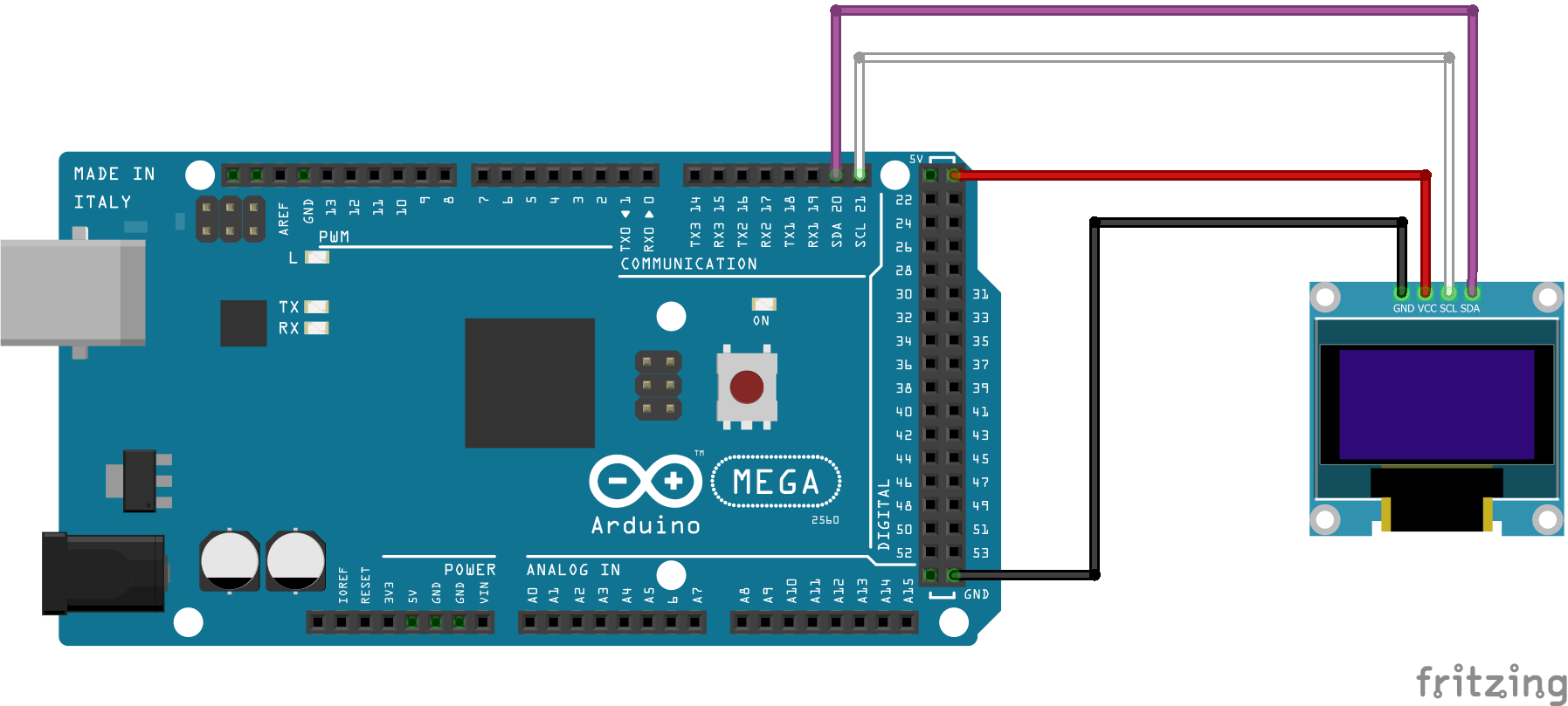
Fig 204: Mega2560 with I2C OLED
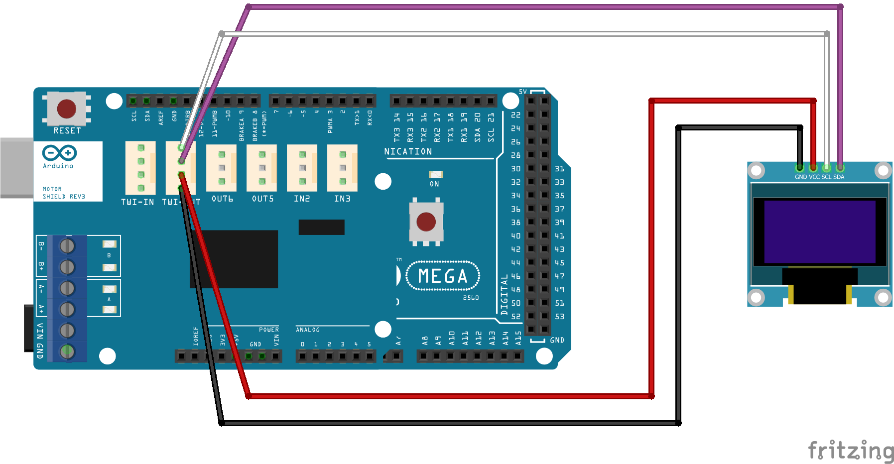
You can also connect the display to the motor shield’s I2C headers.
Reconfigure your Command Station to use a single display
If installing with EX‑Installer, refer to Optional Display to configure a single display with your EX‑CommandStation.
If you are using the Arduino IDE or VSCode with PlatformIO, you will need to edit “config.h” to enable your display option. Look for this section in “config.example.h” to define the display:
/////////////////////////////////////////////////////////////////////////////////////
//
// DEFINE LCD SCREEN USAGE BY THE BASE STATION
//
// Note: This feature requires an I2C enabled LCD screen using a Hitachi HD44780
//       controller and a commonly available PCF8574 based I2C 'backpack'.
// To enable, uncomment one of the #define lines below

// define LCD_DRIVER for I2C address 0x27, 16 cols, 2 rows
// #define LCD_DRIVER  0x27,16,2

//OR define OLED_DRIVER width,height[,address] in pixels (address auto detected if not supplied)
// 128x32 or 128x64 I2C SSD1306-based devices are supported.
// Use 132,64 for a SH1106-based I2C device with a 128x64 display.
// #define OLED_DRIVER 0x3c,128,32

// Define scroll mode as 0, 1 or 2
//  *  #define SCROLLMODE 0 is scroll continuous (fill screen if poss),
//  *  #define SCROLLMODE 1 is by page (alternate between pages),
//  *  #define SCROLLMODE 2 is by row (move up 1 row at a time).
#define SCROLLMODE 1
Uncomment or edit the appropriate line for your display type.
Combine IP address and port on OLED
Note
As this requires modifying part of the EX‑CommandStation software, exercise caution with these edits, and note that it will also prevent installing via EX‑Installer as you will be effectively preventing it from managing the software for you.
To use OLED displays with your EX‑CommandStation, you can save line LCD5 used for the port number and combine it with line LCD4 IP address.
Be aware that the combined IP address and port number can easily exceed 20 characters, which will exceed the display width.
To accomplish this, you will need to edit “WifiInterface.cpp” included with the EX‑CommandStation software. Each time you want to upgrade the software, you will need to repeat this edit.
In “WifiInterface.cpp”, you need to locate the LCD(4...) line (should be around line #313):
LCD(4,F("%s"),ipString); // There is not enough room on some LCDs to put a title to this
Comment out this line by adding // at the beginning, and add this new line immediately below:
// LCD(4,F("%s"),ipString);  // There is not enough room on some LCDs to put a title to this
LCD(4,F("%s:%d"),ipString,port); // *** Single IP:Port
You will also need to comment out the LCD(5...) line by adding // to the beginning (should be around line 317):
// LCD(5,F("PORT=%d"),port);
Once this is done, line 5 onwards are free to use as you wish.
If you have custom messages you wish to display, you can do this by adding the lines to “mySetup.h”:
LCD(5,F("Line 5 custom text"));
LCD(6,F("Line 6 custom text"));
LCD(7,F("Line 7 custom text"));
Configuring Additional Displays
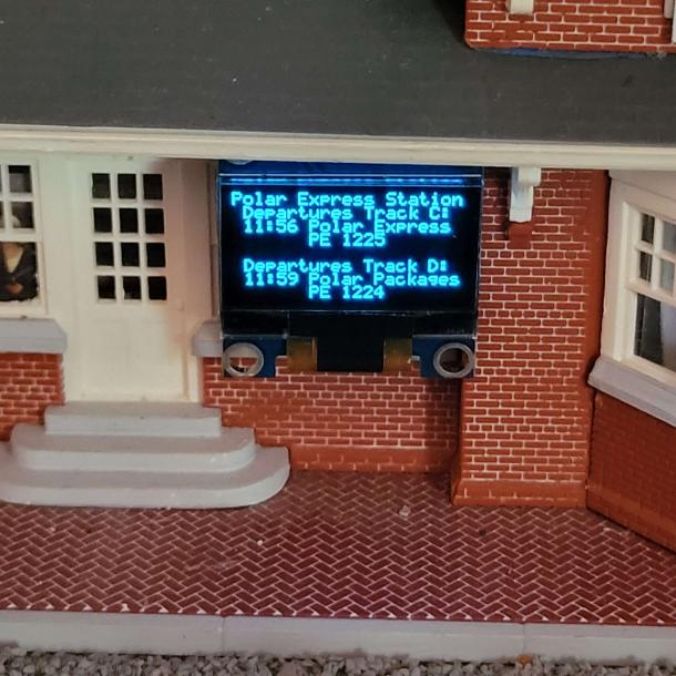
Apart from the main status display (display ‘0’), EX‑CommandStation allows definition of many more additional displays which can be any mix of LCD and OLED I2C displays. These displays can show all manner of output, including using SCREEN() commands issued from within EXRAIL scripts. Here is an OLED showing train departure times on a station building:
In order to configure additional displays, you will need to add lines to “myHal.cpp” in order to create the displays when the command station is running. Below we configure an additional OLED display as display #1, and an LCD as display #2:
// Create a 128x32 OLED display device as display number 1
// (line 0 is written by EXRAIL 'SCREEN(1, 0, "text")').

HALDisplay<OLED>::create(1, 0x3d, 128, 32);

// Create a 20x4 LCD display device as display number 2
// (line 0 is written by EXRAIL 'SCREEN(2, 0, "text")').

HALDisplay<LiquidCrystal>::create(2, 0x27, 20, 4);
As you can see from the comments in this code, both of these displays can now be written to from EXRAIL using the SCREEN() directive. See the EXRAIL Communication and Display Functions for more information.