![]()
Supported Devices


This page outlines the microcontrollers that are supported for use with EX‑IOExpander, including outlining the pins available for use.
When uploading the EX‑IOExpander software, the device type is detected by the compiler in either the Arduino IDE or PlatformIO, so no configuration is necessary on the EX‑IOExpander device itself (aside from the I2C address of course).
All allocation of pins is done via the device driver (see EX-CommandStation device driver).
All Vpins outlined on this page assume use of the default starting Vpin of 800, so you will need to review the Vpin map displayed in the EX‑IOExpander serial console if using a different starting Vpin.
Arduino Nano
Total pins |
18 |
|---|---|
Digital capable pins |
16 |
Analogue capable pins |
6 |
PWM capable pins |
6 |
Vpin |
Pin |
Digital |
Analogue |
PWM |
|---|---|---|---|---|
800 |
2 |
Y |
N |
N |
801 |
3 |
Y |
N |
Y |
802 |
4 |
Y |
N |
N |
803 |
5 |
Y |
N |
Y |
804 |
6 |
Y |
N |
Y |
805 |
7 |
Y |
N |
N |
806 |
8 |
Y |
N |
N |
807 |
9 |
Y |
N |
Y |
808 |
10 |
Y |
N |
Y |
809 |
11 |
Y |
N |
Y |
810 |
12 |
Y |
N |
N |
811 |
13 |
Y |
N |
N |
812 |
A0 |
Y |
Y |
N |
813 |
A1 |
Y |
Y |
N |
814 |
A2 |
Y |
Y |
N |
815 |
A3 |
Y |
Y |
N |
816 |
A6 |
N |
Y |
N |
817 |
A7 |
N |
Y |
N |
Arduino Pro Mini
The Arduino Pro Mini comes in two variations; a 3.3V running at 8MHz, and a 5V running at 16MHz.
Warning
The 8MHz 3.3V Pro Mini is not 5V tolerant
The Pro Mini uses an identical pin map to the Arduino Nano.
Arduino Uno
Total pins |
16 |
|---|---|
Digital capable pins |
16 |
Analogue capable pins |
4 |
PWM capable pins |
6 |
Vpin |
Pin |
Digital |
Analogue |
PWM |
|---|---|---|---|---|
800 |
2 |
Y |
N |
N |
801 |
3 |
Y |
N |
Y |
802 |
4 |
Y |
N |
N |
803 |
5 |
Y |
N |
Y |
804 |
6 |
Y |
N |
Y |
805 |
7 |
Y |
N |
N |
806 |
8 |
Y |
N |
N |
807 |
9 |
Y |
N |
Y |
808 |
10 |
Y |
N |
Y |
809 |
11 |
Y |
N |
Y |
810 |
12 |
Y |
N |
N |
811 |
13 |
Y |
N |
N |
812 |
A0 |
Y |
Y |
N |
813 |
A1 |
Y |
Y |
N |
814 |
A2 |
Y |
Y |
N |
815 |
A3 |
Y |
Y |
N |
Arduino Mega2560
Total pins |
62 |
|---|---|
Digital pins |
62 |
Analogue pins |
16 |
PWM pins |
12 |
Vpin |
Pin |
Digital |
Analogue |
PWM |
Vpin |
Pin |
Digital |
Analogue |
PWM |
|---|---|---|---|---|---|---|---|---|---|
800 |
2 |
Y |
N |
Y |
831 |
35 |
Y |
N |
N |
801 |
3 |
Y |
N |
Y |
832 |
36 |
Y |
N |
N |
802 |
4 |
Y |
N |
Y |
833 |
37 |
Y |
N |
N |
803 |
5 |
Y |
N |
Y |
834 |
38 |
Y |
N |
N |
804 |
6 |
Y |
N |
Y |
835 |
39 |
Y |
N |
N |
805 |
7 |
Y |
N |
Y |
836 |
40 |
Y |
N |
N |
806 |
8 |
Y |
N |
Y |
837 |
41 |
Y |
N |
N |
807 |
9 |
Y |
N |
Y |
838 |
42 |
Y |
N |
N |
808 |
10 |
Y |
N |
Y |
839 |
43 |
Y |
N |
N |
809 |
11 |
Y |
N |
Y |
840 |
44 |
Y |
N |
N |
810 |
12 |
Y |
N |
Y |
841 |
45 |
Y |
N |
N |
811 |
13 |
Y |
N |
Y |
842 |
46 |
Y |
N |
N |
812 |
14 |
Y |
N |
N |
843 |
47 |
Y |
N |
N |
813 |
15 |
Y |
N |
N |
844 |
48 |
Y |
N |
N |
814 |
16 |
Y |
N |
N |
845 |
49 |
Y |
N |
N |
815 |
17 |
Y |
N |
N |
846 |
A0 |
Y |
Y |
N |
816 |
18 |
Y |
N |
N |
847 |
A1 |
Y |
Y |
N |
817 |
19 |
Y |
N |
N |
848 |
A2 |
Y |
Y |
N |
818 |
22 |
Y |
N |
N |
849 |
A3 |
Y |
Y |
N |
819 |
23 |
Y |
N |
N |
850 |
A4 |
Y |
Y |
N |
820 |
24 |
Y |
N |
N |
851 |
A5 |
Y |
Y |
N |
821 |
25 |
Y |
N |
N |
852 |
A6 |
Y |
Y |
N |
822 |
26 |
Y |
N |
N |
853 |
A7 |
Y |
Y |
N |
823 |
27 |
Y |
N |
N |
854 |
A8 |
Y |
Y |
N |
824 |
28 |
Y |
N |
N |
855 |
A9 |
Y |
Y |
N |
825 |
29 |
Y |
N |
N |
856 |
A10 |
Y |
Y |
N |
826 |
30 |
Y |
N |
N |
857 |
A11 |
Y |
Y |
N |
827 |
31 |
Y |
N |
N |
858 |
A12 |
Y |
Y |
N |
828 |
32 |
Y |
N |
N |
859 |
A13 |
Y |
Y |
N |
829 |
33 |
Y |
N |
N |
860 |
A14 |
Y |
Y |
N |
830 |
34 |
Y |
N |
N |
861 |
A15 |
Y |
Y |
N |
STMicroelectronics NUCLEO-F411RE
Warning
Support for the F411RE is experimental at best right now. While the software compiles and it appears to operate normally, only basic I/O testing has been performed.
Note also that as a 3.3V microcontroller, not all pins are 5V tolerant.
The Nucleo F411RE is a 3v3 microcontroller with more available I/O pins than an Arduino Uno in a similar, but slightly larger form factor. The pin numbers used are defined using the Morpho pin names associated with connectors CN7 and CN10.
Vpins are allocated in ascending order from the STLink/USB connector end of each Morpho connector, with the odd numbered pin row first, then the even number row, hence the pin names aren’t sequential.
Numerous I/O pins are connected to other devices or perform multiple functions which result in pin conflicts, so the only pins included are those that are able to successfully be set to input mode on startup.
Note
PC13 has a switch (blue button) with pullup resistor attached, so this is suitable as an input only (without pullups enabled) unless you disconnect SB17.
In addition, PA5 is the green LED.
Total pins |
40 |
|---|---|
Digital pins |
40 |
Analogue pins |
14 |
PWM pins |
25 |
Vpin |
Pin |
Digital |
Analogue |
PWM |
Vpin |
Pin |
Digital |
Analogue |
PWM |
|---|---|---|---|---|---|---|---|---|---|
800 |
PC10 |
Y |
N |
N |
820 |
PC7 |
Y |
N |
Y |
801 |
PC12 |
Y |
N |
N |
821 |
PA9 |
Y |
Y |
Y |
802 |
PA15 |
Y |
N |
Y |
822 |
PA8 |
Y |
N |
Y |
803 |
PB7 |
Y |
N |
Y |
823 |
PB10 |
Y |
N |
Y |
804 |
PC15 |
Y |
N |
N |
824 |
PB4 |
Y |
N |
Y |
805 |
PC2 |
Y |
N |
N |
825 |
PB5 |
Y |
N |
Y |
806 |
PC3 |
Y |
N |
N |
826 |
PB3 |
Y |
N |
Y |
807 |
PC11 |
Y |
Y |
N |
827 |
PA10 |
Y |
N |
Y |
808 |
PD2 |
Y |
Y |
N |
828 |
PC8 |
Y |
N |
N |
809 |
PA0 |
Y |
Y |
Y |
829 |
PC6 |
Y |
N |
Y |
810 |
PA1 |
Y |
Y |
Y |
830 |
PC5 |
Y |
Y |
N |
811 |
PA4 |
Y |
Y |
N |
831 |
PA12 |
Y |
N |
N |
812 |
PB0 |
Y |
Y |
Y |
832 |
PA11 |
Y |
N |
Y |
813 |
PC1 |
Y |
Y |
N |
833 |
PB12 |
Y |
N |
N |
814 |
PC0 |
Y |
Y |
N |
834 |
PB2 |
Y |
N |
N |
815 |
PC9 |
Y |
N |
Y |
835 |
PB1 |
Y |
N |
Y |
816 |
PA5 |
Y |
N |
Y |
836 |
PB15 |
Y |
N |
Y |
817 |
PA6 |
Y |
N |
Y |
837 |
PB14 |
Y |
N |
Y |
818 |
PA7 |
Y |
Y |
Y |
838 |
PB13 |
Y |
N |
Y |
819 |
PB6 |
Y |
Y |
Y |
839 |
PC4 |
Y |
Y |
N |
STMicroelectronics NUCLEO-F412ZG
Warning
Support for the F412ZG is experimental at best right now. While the software compiles and it appears to operate normally, only basic I/O testing has been performed.
Note also that as a 3.3V microcontroller, not all pins are 5V tolerant.
The Nucleo F412ZG is a 3v3 microcontroller with significantly more available I/O pins than an Arduino Mega. The pin numbers used are defined using the Morpho pin names associated with connectors CN11 and CN12.
Vpins are allocated in ascending order from the STLink/USB connector end of each Morpho connector, with the odd numbered pin row first, then the even number row, hence the pin names aren’t sequential.
Numerous I/O pins are connected to other devices or perform multiple functions which result in pin conflicts, so the only pins included are those that are able to successfully be set to input mode on startup.
Note
PC13 has a switch (blue button) with pullup resistor attached, so this is suitable as an input only (without pullups enabled) unless you disconnect SB17.
In addition, PB0 is the green LED, PB7 is the blue LED, and PB14 in the red LED.
Total pins 97 |
97 |
|---|---|
Digital pins |
97 |
Analogue pins |
16 |
PWM pins |
40 |
Vpin |
Pin |
Digital |
Analogue |
PWM |
Vpin |
Pin |
Digital |
Analogue |
PWM |
|---|---|---|---|---|---|---|---|---|---|
800 |
PC10 |
Y |
N |
N |
849 |
PB6 |
Y |
Y |
Y |
801 |
PC12 |
Y |
N |
N |
850 |
PC7 |
Y |
Y |
Y |
802 |
PF6 |
Y |
N |
N |
851 |
PB10 |
Y |
Y |
Y |
803 |
PF7 |
Y |
N |
N |
852 |
PB4 |
Y |
N |
N |
804 |
PA15 |
Y |
N |
Y |
853 |
PB5 |
Y |
N |
Y |
805 |
PB7 |
Y |
N |
Y |
854 |
PB3 |
Y |
N |
Y |
806 |
PC13 |
Y |
N |
Y |
855 |
PA2 |
Y |
N |
Y |
807 |
PC2 |
Y |
N |
Y |
856 |
PA3 |
Y |
N |
N |
808 |
PC3 |
Y |
N |
N |
857 |
PD13 |
Y |
Y |
Y |
809 |
PD4 |
Y |
Y |
Y |
858 |
PD12 |
Y |
N |
Y |
810 |
PD5 |
Y |
Y |
Y |
859 |
PD11 |
Y |
N |
Y |
811 |
PD6 |
Y |
Y |
N |
860 |
PE10 |
Y |
N |
Y |
812 |
PD7 |
Y |
Y |
Y |
861 |
PE12 |
Y |
N |
Y |
813 |
PE3 |
Y |
Y |
N |
862 |
PE14 |
Y |
N |
Y |
814 |
PF1 |
Y |
Y |
N |
863 |
PE15 |
Y |
N |
Y |
815 |
PF0 |
Y |
Y |
N |
864 |
PE13 |
Y |
N |
Y |
816 |
PD1 |
Y |
Y |
N |
865 |
PF13 |
Y |
Y |
N |
817 |
PD0 |
Y |
N |
N |
866 |
PF12 |
Y |
Y |
Y |
818 |
PG0 |
Y |
N |
N |
867 |
PG14 |
Y |
N |
N |
819 |
PE1 |
Y |
N |
N |
868 |
PD10 |
Y |
Y |
Y |
820 |
PG9 |
Y |
N |
N |
869 |
PG4 |
Y |
N |
N |
821 |
PG12 |
Y |
N |
N |
870 |
PC8 |
Y |
N |
Y |
822 |
PC11 |
Y |
N |
N |
871 |
PC6 |
Y |
N |
Y |
823 |
PD2 |
Y |
N |
N |
872 |
PC5 |
Y |
N |
N |
824 |
PA0 |
Y |
N |
N |
873 |
PB12 |
Y |
N |
Y |
825 |
PA1 |
Y |
N |
N |
874 |
PB11 |
Y |
N |
N |
826 |
PA4 |
Y |
N |
N |
875 |
PB2 |
Y |
N |
N |
827 |
PB0 |
Y |
N |
Y |
876 |
PB1 |
Y |
N |
Y |
828 |
PC1 |
Y |
N |
N |
877 |
PB15 |
Y |
N |
Y |
829 |
PC0 |
Y |
N |
N |
878 |
PB14 |
Y |
N |
Y |
830 |
PD3 |
Y |
N |
N |
879 |
PB13 |
Y |
N |
Y |
831 |
PG2 |
Y |
N |
Y |
880 |
PC4 |
Y |
N |
N |
832 |
PG3 |
Y |
N |
N |
881 |
PF5 |
Y |
N |
Y |
833 |
PE2 |
Y |
N |
Y |
882 |
PF4 |
Y |
N |
Y |
834 |
PE4 |
Y |
N |
N |
883 |
PE8 |
Y |
N |
N |
835 |
PE5 |
Y |
N |
N |
884 |
PF10 |
Y |
N |
Y |
836 |
PF2 |
Y |
N |
N |
885 |
PE7 |
Y |
N |
Y |
837 |
PF8 |
Y |
N |
N |
886 |
PD14 |
Y |
N |
N |
838 |
PF9 |
Y |
N |
Y |
887 |
PD15 |
Y |
N |
N |
839 |
PG1 |
Y |
N |
N |
888 |
PF14 |
Y |
N |
N |
840 |
PE6 |
Y |
N |
N |
889 |
PE9 |
Y |
N |
N |
841 |
PG15 |
Y |
N |
N |
890 |
PE11 |
Y |
N |
N |
842 |
PG10 |
Y |
N |
N |
891 |
PF3 |
Y |
N |
N |
843 |
PG13 |
Y |
N |
N |
892 |
PF15 |
Y |
N |
N |
844 |
PG11 |
Y |
N |
N |
893 |
PF11 |
Y |
N |
N |
845 |
PC9 |
Y |
N |
Y |
894 |
PE0 |
Y |
N |
N |
846 |
PA5 |
Y |
N |
Y |
895 |
PG8 |
Y |
N |
N |
847 |
PA6 |
Y |
N |
Y |
896 |
PG5 |
Y |
N |
N |
848 |
PA7 |
Y |
Y |
N |
Arduino Zero (or SAMD based clone)
Warning
The Arduino Zero (and SAMD based clones) are 3v3 only and are not 5V tolerant.
Support for the Arduino Zero (or other SAMD clones) is experimental at best right now. While the software compiles and it appears to operate normally, no actual I/O testing has been performed.
Total pins 27 |
Minimum |
Maximum |
|---|---|---|
Digital pins |
21 |
27 |
Analogue pins |
0 |
6 |
Vpins |
800 |
801 |
802 |
803 |
804 |
805 |
806 |
807 |
|---|---|---|---|---|---|---|---|---|
Digital Pins |
0 |
1 |
2 |
3 |
4 |
5 |
6 |
7 |
Vpins |
808 |
809 |
810 |
811 |
812 |
813 |
814 |
815 |
Digital Pins |
8 |
9 |
10 |
11 |
12 |
13 |
22 |
23 |
Vpins |
812 |
813 |
814 |
815 |
816 |
|||
Digital Pins |
24 |
38 |
39 |
40 |
41 |
|||
Vpins |
817 |
818 |
819 |
820 |
821 |
822 |
||
Analogue Pins |
A0 |
A1 |
A2 |
A3 |
A5 |
A6 |
STMicroelectronics STM32F103C8T6 (Bluepill)
Warning
Support for the STM32F103C8T6 Bluepill is experimental at best right now. While the software compiles and it appears to operate normally, only basic I/O testing has been performed.
Note also that as a 3.3V microcontroller, not all pins are 5V tolerant.
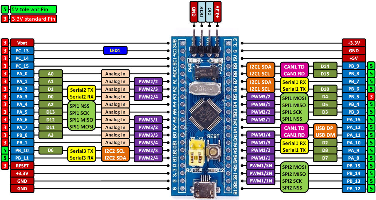
Image courtesy of arm MBED 
Total pins |
28 |
|---|---|
Digital capable pins |
28 |
Analogue capable pins |
10 |
PWM capable pins |
19 |
Vpin |
Pin |
Digital |
Analogue |
PWM |
Vpin |
Pin |
Digital |
Analogue |
PWM |
|---|---|---|---|---|---|---|---|---|---|
800 |
PC13 |
Y |
N |
N |
814 |
PB11 |
Y |
N |
Y |
801 |
PC14 |
Y |
N |
N |
815 |
PB9 |
Y |
N |
N |
802 |
PA15 |
Y |
N |
N |
816 |
PB8 |
Y |
N |
N |
803 |
PA0 |
Y |
Y |
N |
817 |
PB5 |
Y |
N |
Y |
804 |
PA1 |
Y |
Y |
Y |
818 |
PB4 |
Y |
N |
Y |
805 |
PA2 |
Y |
Y |
Y |
819 |
PB3 |
Y |
N |
Y |
806 |
PA3 |
Y |
Y |
Y |
820 |
PA15 |
Y |
N |
Y |
807 |
PA4 |
Y |
Y |
N |
821 |
PA10 |
Y |
N |
Y |
808 |
PA5 |
Y |
Y |
N |
822 |
PA9 |
Y |
N |
Y |
809 |
PA6 |
Y |
Y |
Y |
823 |
PA8 |
Y |
N |
Y |
810 |
PA7 |
Y |
Y |
Y |
824 |
PB15 |
Y |
N |
Y |
811 |
PB0 |
Y |
Y |
Y |
825 |
PB14 |
Y |
N |
Y |
812 |
PB1 |
Y |
Y |
Y |
826 |
PB13 |
Y |
N |
Y |
813 |
PB10 |
Y |
N |
Y |
827 |
PB12 |
Y |
N |
N |
Adding new devices
Warning
When considering adding new devices to EX‑IOExpander, be sure to take into account whether they are 5V or 3.3V devices, and whether their I/O and I2C pins are 5V tolerant if they are 3.3V devices. New generation microcontrollers tend to be 3.3V, and some have 5V tolerant I/O pins (e.g. STM32 Nucleo), but some are not 5V tolerant (e.g. SAMD).
To connect 3.3V devices to a 5V EX‑CommandStation, they need to either be 5V tolerant, or you will need to use a level shifter to avoid letting the magic smoke out.
Adding new devices to the EX‑IOExpander software only requires additional information in the EX‑IOExpander software itself, with no changes required to the device driver loaded in your EX‑CommandStation.
In order to successfully add an additional device, you need to know the C++ preprocessor macro definitions for the architecture or platform, and for the specific variant or board itself. In addition, you need to define the pins available for use on the EX‑IOExpander device, and define the capabilities available for each pin.
For example, the AVR series (Uno, Mega, Nano) have the architecture or platform macro defined as “ARDUINO_ARCH_AVR”, with the Nano having the variant or board specific macro “ARDUINO_AVR_NANO”, and there is a pin map defined that maps to this macro definition.
Files to be created/modified
When adding new devices to EX‑IOExpander, there are potentially three files to be added or modified:
device_functions.cpp - Contains the architecture/platform specific function to reboot via software
defines.h - Contains some device specific macro definitions
<device_type>.h - Contains the device specific macro definitions and the pin map
EX-IOExpander.ino - Loads the device specific files
Enabling software reboots
The architecture or platform macro is used to determine the correct method to reboot the device via the <Z> command, which is defined in the file “device_functions.cpp”.
If a new architecture or platform is being added, then this file will need to be updated with the suitable software command in the “reset()” function, otherwise a reboot via <Z> will not be available.
If the architecture or platform already exists, or there is no desire to reboot via software, then the only change required is to add the variant or board specific information.
Enabling serial input/output in defines.h
Some microcontrollers have different serial implementations, and therefore it may be necessary to specify the type of USB or serial port in use.
Currently, unless the device’s architecture is defined as “ARDUINO_ARCH_SAMD”, it will utilise the default Arduino “Serial” implementation. SAMD uses the “SerialUSB” implementation.
If additional serial support is required, this will need to be defined in “defines.h” as “USB_SERIAL”.
Defining the device macros in defines.h
There are three parameters to be defined in this file for each device type:
TOTAL_PINS - The total number of pins available on the device
NUM_PWM_PINS - The number of pins with PWM capability
HAS_EEPROM - Define only if the device has EEPROM capability
These need to be defined according to the CPU type macro definition. For example an Arduino Uno is defined as:
//  Arduino Uno
#elif defined(ARDUINO_AVR_UNO)
#define TOTAL_PINS 16
#define NUM_PWM_PINS 6
#define HAS_EEPROM
#elif ...
Defining the device type and pin map in <device_name>.h
A pin map is used to map the Vpins from the device driver in the EX‑CommandStation to the appropriate physical pins on the EX‑IOExpander device, and therefore defining this in the correct order in the EX‑IOExpander software is critical. It is equally critical to ensure that the correct variant or board macro is used to ensure the correct pin map is used when compiling and uploading the software to the EX‑IOExpander device.
Each unique device needs a file created containing the “BOARD_TYPE” macro definition and the device specific pin map.
Files should be named according to the platform and CPU type e.g. “arduino_avr_nano.h” or “arduino_nucleo_f412zg.h”.
As per Pin/Vpin allocation, Vpins are allocated to physical pins in ascending order.
These are the considerations when defining the pin map:
All pins available for use must be represented in a logical order to provide the simplest user experience
The capability for each pin must be provided according to the Pin capability table
The number of defined pins must match “TOTAL_PINS” as defined in “defines.h”
The number of pins defined with PWM capability must match “NUM_PWM_PINS” as defined in “defines.h”
Further to this, if the microcontroller utilises internal I2C pullup resistors rather than external, physical resistors, then the I2C pins can be defined to allow these to be disabled via “myConfig.h” (see DISABLE_I2C_PULLUPS).
To use the Arduino Uno as the example, the file “arduino_avr_uno.h” would be created with these contents:
#ifndef ARDUINO_AVR_UNO_H
#define ARDUINO_AVR_UNO_H

#include <Arduino.h>
#include "globals.h"

#define BOARD_TYPE F("Uno")
pinDefinition pinMap[TOTAL_PINS] = {
  {2,DIO},{3,DIOP},{4,DIO},{5,DIOP},{6,DIOP},{7,DIO},
  {8,DIO},{9,DIOP},{10,DIOP},{11,DIOP},{12,DIO},{13,DIO},
  {A0,AIDIO},{A1,AIDIO},{A2,AIDIO},{A3,AIDIO},
};
#define I2C_SDA A4
#define I2C_SCL A5

#endif
All C++ header (.h) files should include a header guard, which is the first two lines, and file “#ifdef”
You must include the Arduino library and “globals.h” file
The “BOARD_TYPE” is displayed in the serial console at startup as “Uno”
All available pins are defined with their capability
Arduino Nano uses internal I2C pullup resistors, and therefore defining the I2C pins A4/A5 allows these to be disabled via “myConfig.H” if desired
Pin capability table
When defining the capabilities available for a specific pin, one of these macros from this table must be utilised. These capability macros are defined in “defines.h”.
This ensures attempting to use a pin for something it’s not capable of will generate an error rather than try to drive a pin with capability that is not possible, as depending on the scenario, this may let the magic smoke out.
Macro |
Capabilities |
|---|---|
NA |
Not suitable for use |
DI |
Digital input only |
DO |
Digital output only |
DIO |
Digital input and output |
AI |
Analogue input only |
AIDI |
Analogue and digital input |
AIDO |
Analogue input and digital output |
AIDIO |
Analogue input with digital input and output |
P |
PWM output only |
DIP |
Digital input and PWM output |
DOP |
Digital output and PWM output |
DIOP |
Digital input and output with PWM output |
AIP |
Analogue input and PWM output |
AIDIP |
Analogue input with digital input and PWM output |
AIDOP |
Analogue input with digital output and PWM output |
AIDIOP |
Analogue input with digital input and output and PWM output |