![]()

EX-CSB1 Quick Setup Guide


EX‑CommandStation / Booster One Express
This quick startup guide is designed to have you configured and setup to run trains in 5 minutes. After all, the point is to enjoy running trains, not sifting through more information than you need until you are ready.
These instructions are for DCC locomotives. For more detailed information, to configure for running DC trains, or to use different throttles like EX‑WebThrottle or JMRI, see the EX-CSB1 Operating Manual
What You Will Need
A Power supply (12-16v DC see Power Supplies) [2]
A DCC loco (If you are here to run DC locos, please go to the TrackManager (DCC & DC) page.)
Some Track
16 to 28AWG/1.5mm^2 Wire, preferably in 2 colours with 1/8”/6mm insulation stripped (and wire tinned if stranded)
Jeweller’s flat bladed screwdriver (1.5 - 2mm blade)
A WiFi capable smart device like a phone or tablet to control your trains (aka a “Throttle”)
Board Layout
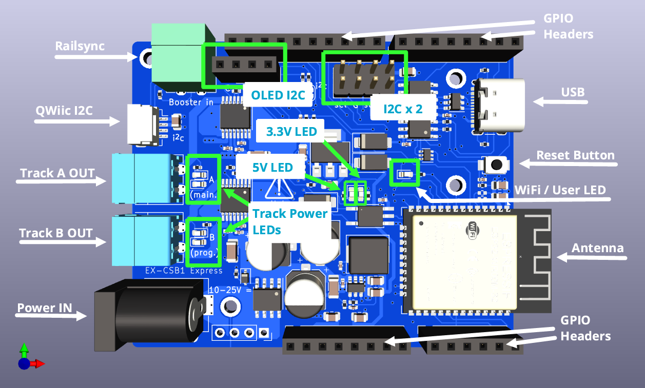
Fig 228: EX-CSB1 top (click image to enlarge it)
A full explanation of the board is available in the manual.
Warning
Start with all power disconnected!!
Before connecting any wires to your command station or tracks, make sure you have unplugged the power supply from the wall or removed the barrel connector from the command station.
It is crucial to ensure that the command station has no power while you are working on your connections.
Summary or Super-Quick Start
In summary, you need just two basic wiring connections to the EX‑CommandStation / Booster One Express to be up and running trains:
Track connected to Track A Output
Power supply input connected to Power IN DC barrel jack
And to connect via WiFi to the EX‑CSB1 to control trains your smart device will need either:
Engine Driver or EX‑Toolbox for Android
wiThrottle for Apple iOS
These are the most basic steps to get you up and running. If you need more help, then remainder of this page explains these steps in much greater detail.
Steps
1. Connect your EX-CSB1 to your track
Connect your main track to the
AMAIN output to your Command Station.2. Connect power to your EX-CSB1
3. Connect Your Smart Device(Phone) to the ‘DCCEX_xxxxx’ WiFi Network
An Android Phone or Tablet or Apple iOS Phone or Tablet can be used.
Open the Wifi Settings in your smart device.
Select the WiFi network in your smart device WiFi settings named
DCCEX_xxxxxx, and use the corresponding passwordPASS_xxxxxx(where xxxxxx is identical in each case) which is shown on your EX-CSB1’s OLED display.Tell your smart device not to worry about there being no Internet connection. [4]
4. Connect Your Controller (Throttle) App to the ‘dccex’ Server
Launch your throttle app. [5]
In your throttle app, connect to the
dccexserver.5. Acquire a Loco in Your Controller (Throttle) App
Place a working DCC equiped loco, with a known DCC Address, on the track
Acquire that loco using its DCC Address
6. Run Trains
Run/control the loco
These quick tips may have been be enough to get your running, but step by step instructions follow below.
Connecting your Command Station
Track Connection
There are 2 track output power connectors marked A and B. In the standard DCC-EX configuration of a EX‑CSB1, A is configured for DCC MAIN operation, and B is configured for PROG or programming track output.
We recommend connecting your track to the A MAIN output initially to test your Command Station.
To alter this default configuration of DCC outputs, or for DC Mode, you would need to configure outputs with a TrackManager command in the mySetup.h file or by creatine a ‘Route’. See the TrackManager page for details.
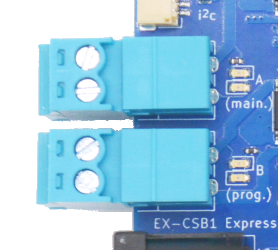
Fig 229: Track A and B Outputs
The pluggable male screw terminals accept to 16 to 28 AWG/1.5mm^2 gauge solid or stranded wire.
If you use stranded wire, we recommend “tinning” the ends of the wire to make a good connection and ensure that stray wire whiskers don’t stray outside the screw terminals and cause a short circuit.
Larger wire can handle more current and provide less resistance. 18-22 AWG usually good. Keep your wires short by mounting the Command Station close to the track.
Using a small flat-bladed screwdriver, loosen both screws on the MAIN (A) Track Output being careful not to screw them all the way out. The screws just need to be loosened enough to fit your wires into the holes. Tighten down both screws once you have inserted the wires making sure to not overtighten.
You can pull the connector out of its socket to remove it from the EX‑CSB1 to make this easier. Remember push the connector all the way into the connector on the board to snap it back in place.
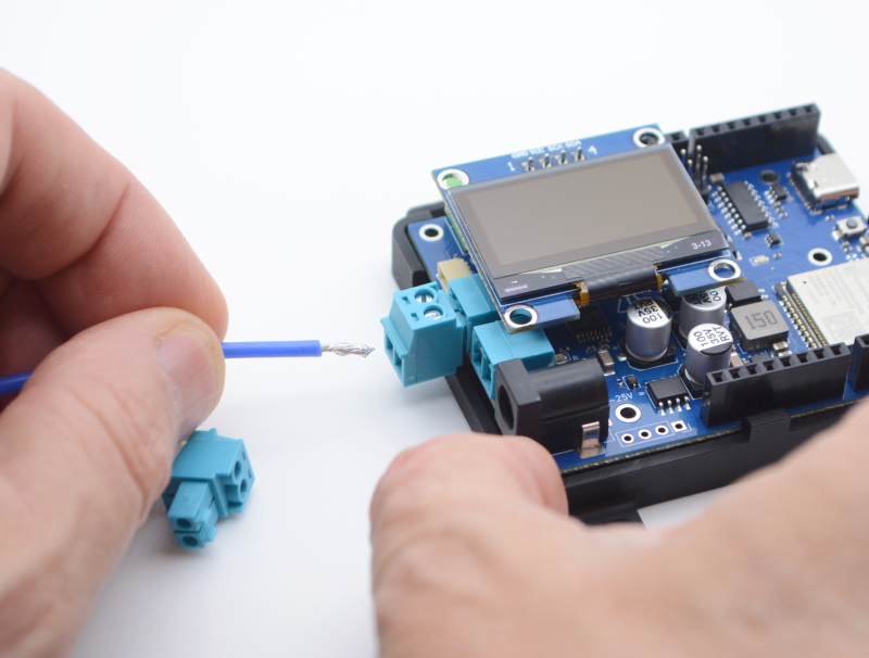
Fig 230: Inserting wires
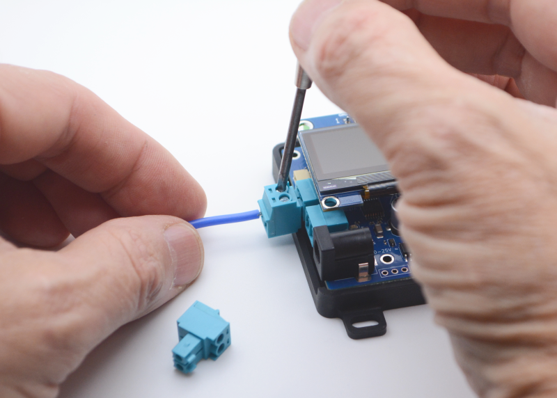
Fig 231: Tightening Screws
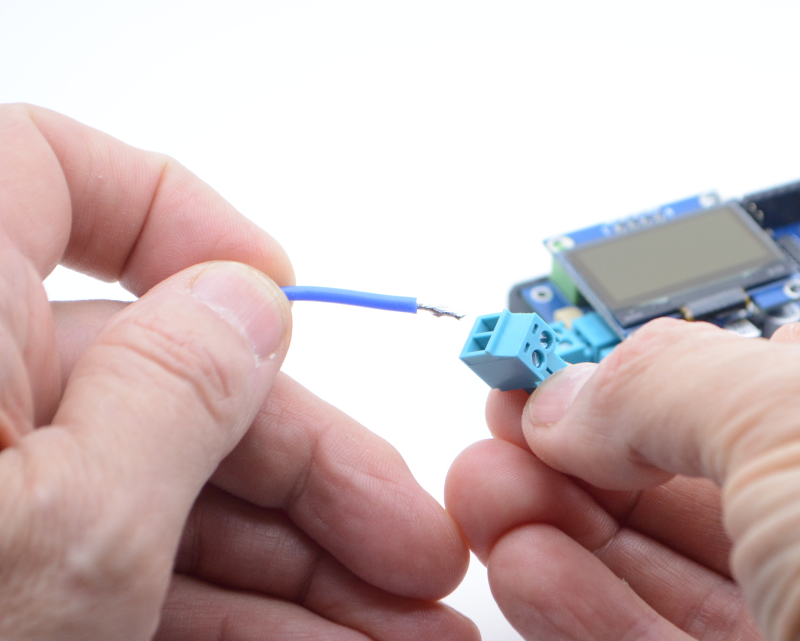
Fig 232: Optionally unplugging connector to insert wires
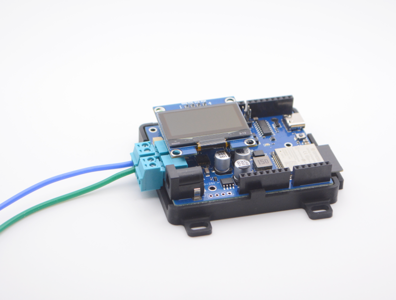
Fig 233: Wires properly inserted and plug inserted
Note
The power connection to your track will be either wires you solder yourself to the rails or via a power connector that plugs into track (such as Kato Unitrack). We will leave it up to you to determine the proper connection to your track.
Connect the other ends of the track output wires to your track. While not critical at this stage when using DCC. It is best to keep to a standard where the RED wire (or striped wire) is connected to the outside rail of the track to make things easier when using feeders to track sections or adding reversing loops.
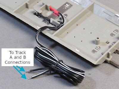
Fig 234: Connecting Wires to Track
Power Connection
The EX‑CSB1 has a 2.1mm x 5.5mm power jack. If you already have a power supply with bare wires, you can use an optional 2.1mm x 5.5mm screw terminal block adapter.
For N you would normally use a 12v to 14v power supply and HO scale you would normally use a 12v to 16v DC power supply, but be sure to check the manual for your loco/decoder combination for the correct voltage [6].
For more information about power supplies, including how to use one power supply to supply all the different voltages on your layout, see Power Supplies.
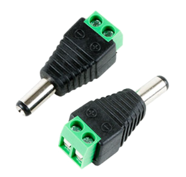
Fig 235: 2.1mm Screw
Terminal Adapter
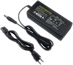
Fig 236: 12v/3A Power Supply
Testing Your Command Station
Connect Track Input Power
To fully power the EX‑CommandStation / Booster One Express, just plug your power supply into the mains power (aka wall outlet) and connect the barrel end to the Command Station.
Make sure your power supply matches the needs of your setup: the voltage should be between 12v and 25v DC, depending on the scale of your locomotives [7], and it should provide at least 2A of current with good over-current performance and voltage stability.
To get the most out of your EX‑CSB1 we suggest using a modern switching power supply with 4A or more. For Z scale, 12v is usually enough, but for N we recommend using between 12v and 14v, and for HO/OO scales we recommend using between 14v and 16v DC [7].
It’s important that your DC power is well-regulated which is why we suggest a modern switch-mode power supply with double insulation and strong overload protection.
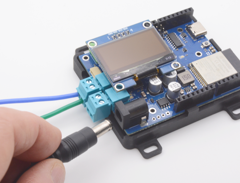
Fig 237: Inserting Power Supply Barrel Plug
When you connect power to the EX‑CSB1 via the barrel connector, you should see both bright green power LEDs light up (5V and 3.3V power), confirming that the electronics are working.
However, for safety, track output power will be off by default when you first plug in the EX‑CSB1. This is to prevent power from accidentally being applied to your layout before everything is ready. If you prefer, you can change this default setting in the Startup Configuration.
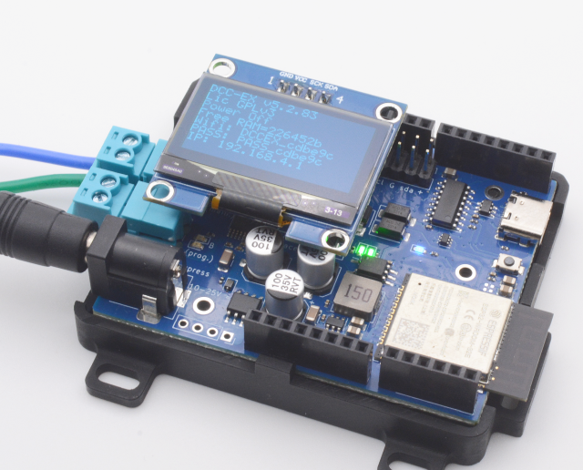
Fig 238: Barrel Plug Power LEDs
You should see status information on the display including the EX‑CSB1 firmware version, track power status, free memory, and WiFi connection information.
If you do not have a display, you will need to connect a Serial Monitor to see the status, but this is not essential for ongoing use of the system. (See: Using a Serial Monitor).
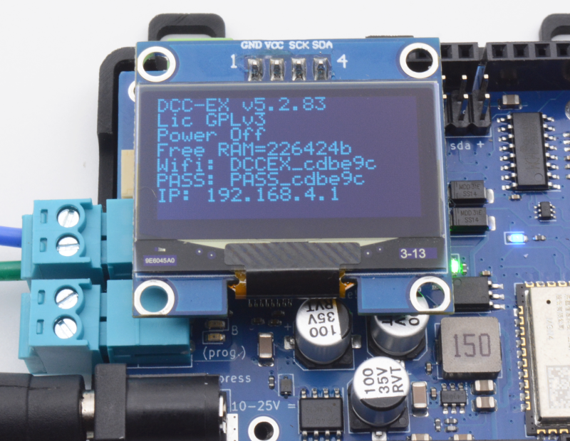
Fig 239: OLED Status Display
Connecting Your Throttle (controller)
Connect the Smart Device to the EX-CSB1 AP Network
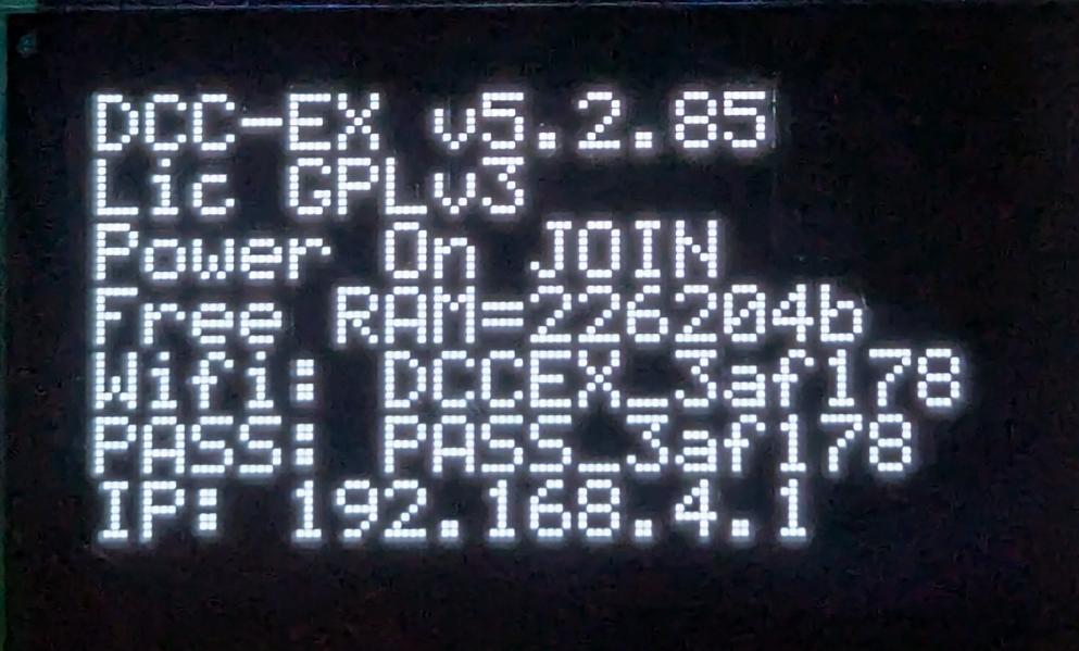
Fig 240: EX-CSB1 Startup - OLED screen
The EX‑CommandStation / Booster One Express will power up in WiFi Access Point mode as configured out of the box, with its own unique WiFi network SSID of DCCEX_xxxxxx and password of PASS_xxxxxx (where xxxxxx is the last 6 digits of the MAC address of the EX‑CSB1), both of which will be visible on the OLED display (or Serial Monitor log). After it boots you can connect with a WiFi throttle like Engine Driver or wiThrottle.
This quick start covers initial testing with the Engine Driver app, though it is a broadly similar process when using any other throttle app on a Smart device.
For a USB Connection with EX‑WebThrottle or JMRI and a computer, please see the full CSB1 operating manual.
Access Point (AP) mode creates a separate WiFi network on the Command Station itself, whereas Station (STA) mode allows the Command Station to join as a WiFi device on your home or layout WiFi network. We have the EX‑CSB1 set to default to Access Point (AP) mode for the convenience of being able to get up and running quickly.
To configure your EX‑CSB1 to connect to your home network, see WiFi Configuration.
The WiFi LED will illuminate once WiFi is configured and ready as an Access Point (or Station if reconfigured for STA mode.)
In your smart device’s system WiFi settings, select the network settings and find an available network that begins with “DCCEX_”.
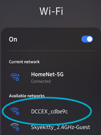
Fig 241: Smart Device Available Networks Screen
Click on that network to see the next screen to enter your password. Notice the password is just “PASS_” followed by the same 6 digits in the network name (called a “SSID”).
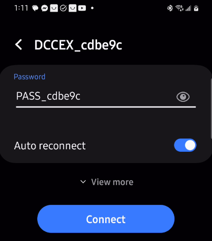
Fig 242: Smart Device AP Password Entry
Run the Engine Driver Setup Wizard
Open the Engine Driver app on your Android smart device:
Fig 243: Engine Driver App Icon
The very first time the app is launched the “Welcome to Engine Driver” Intro/Setup Wizard is shown. The wizard will ask to grant the app the required permissions and allow you to select some basic preferences for the theme and throttle layout.
If you have already used Engine Driver, you can run the wizard again at any time from the app menu (from the ‘Connection’ screen only). Any settings from previous runs of the wizard will be maintained.
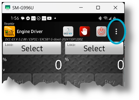
Fig 244: Engine Driver App Menu
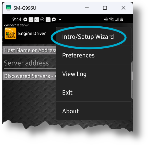
Fig 245: Engine Driver Intro/Setup Wizard
The Wizard allows you to set or change appearance options and, most importantly, choose to use DCC-EX Native Commands instead of wiThrottle Protocol:
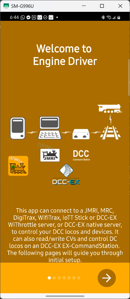
Fig 246: Engine Driver Wizard Opening Screen
Scroll through the other screens setting your preferences until you get the the DCC-EX screen and make sure to select the option to use an EX-CommandStation.
This setting will automatically add useful buttons and switch to using the DCC-EX Native Commands instead of wiThrottle Protocol (you can always switch back and forth if you need to connect to a WiThrottle specific device):
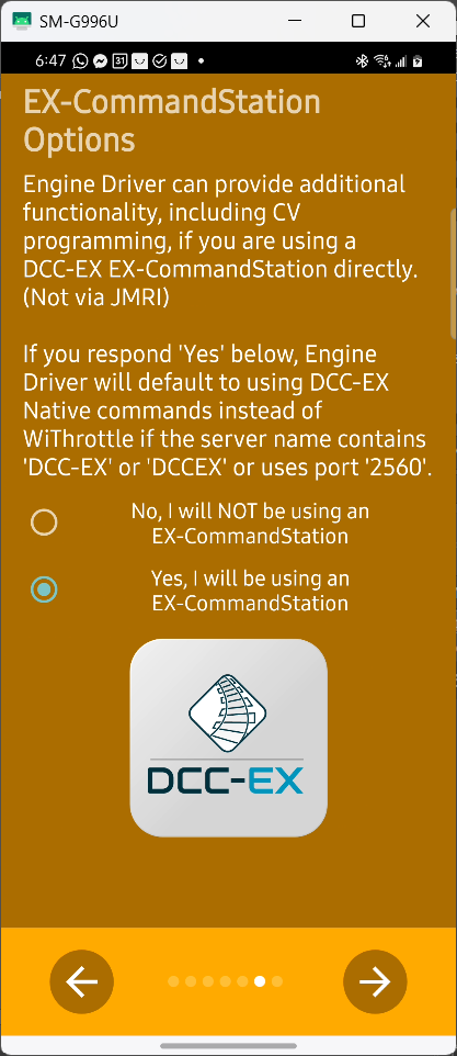
Fig 247: Engine Driver Wizard DCC-EX Select
After choosing the DCC-EX option above and pressing the checkmark to finish the Wizard, the opening Engine Driver screen will change to look like Figure: DCC-EX Protocol Bottom Selector below with an added option at the bottom of the screen for ‘Connection Protocol’.
‘Auto’ for Automatic is now the default.
You can manually switch between DCC-EX Native Protocol and wiThrottle Protocol if you go to a club or use another type of Command Station that requires the wiThrottle Protocol, but generally the ‘Auto’ setting will do so automatically.
The DCC-EX Native Protocol allows for more powerful, expanded capabilities when connected to an EX‑CommandStation:
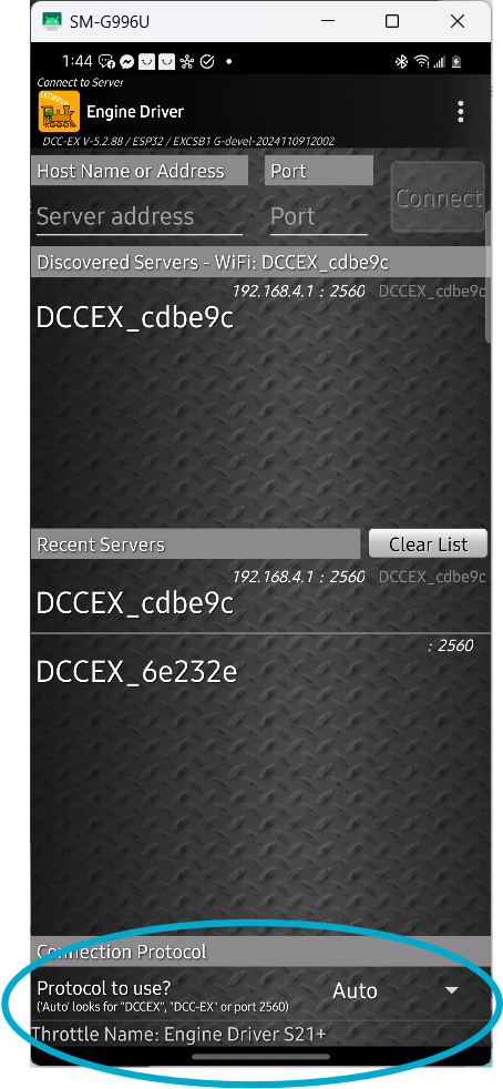
Fig 248: DCC-EX Protocol Bottom Selector
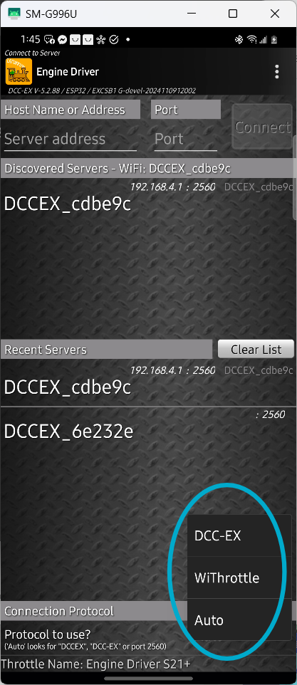
Fig 249: DCC-EX Protocol Menu
Connect Engine Driver to EX-CommandStation
Engine Driver should find the Command Station automatically and show it’s SSID in the ‘Discovered Servers’ List. Simply select yours by clicking on it. The last 6 characters of the SSID will be unique to your Command Station.
If the list is empty, try entering it manually by putting 192.168.4.1 in the ‘Server Address’ and 2560 for the ‘Port’. If that still does not work, see the Section on WiFi here todo XXX.
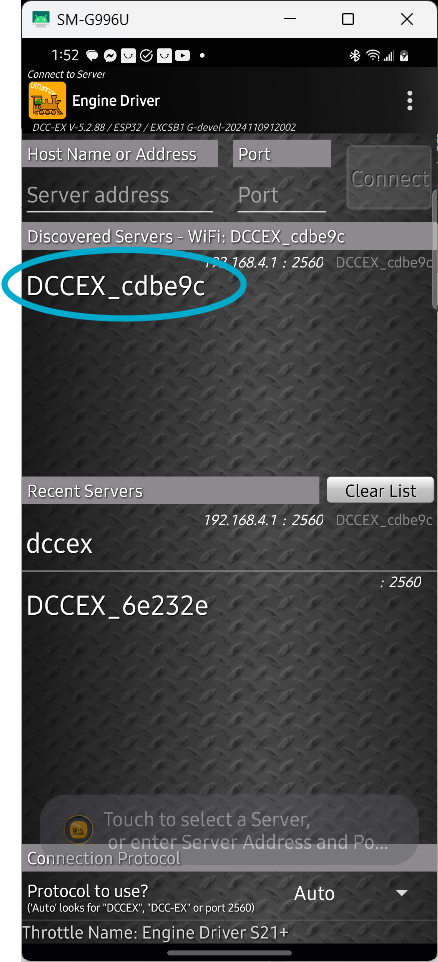
Fig 250: Command Station Connect
Acquire Your Loco
Once you have connected to your command station, the next screen will display the throttle controls. They will be greyed out until you select a loco to control.
Press the select button and enter the address for your loco. Here you can see we are acquiring loco 3 (the default address for almost all locos as they come from the box).
(Once you are happy that your EX‑CommandStation is fully functioning you can change the DCC address of your locos using these instructions.)
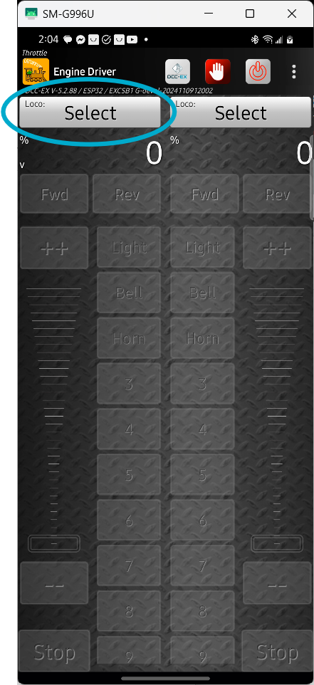
Fig 251: Press Loco Select Button
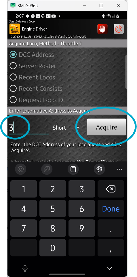
Fig 252: Acquire Loco by its address
The throttle screen reappears and the controls are active. You will also see 3 icons at the top of the display, a special DCC-EX button, an ‘emergency stop’ button, and a ‘track power’ button.
Press the red ‘power’ button to turn on the track power, the button should turn green and your track power should be on (the track output LEDs on your motor driver should light).
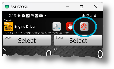
Fig 253: Turn On Track Power
Run Trains
Move the slider control up slowly, operate the horn and light buttons, and you should be running trains!
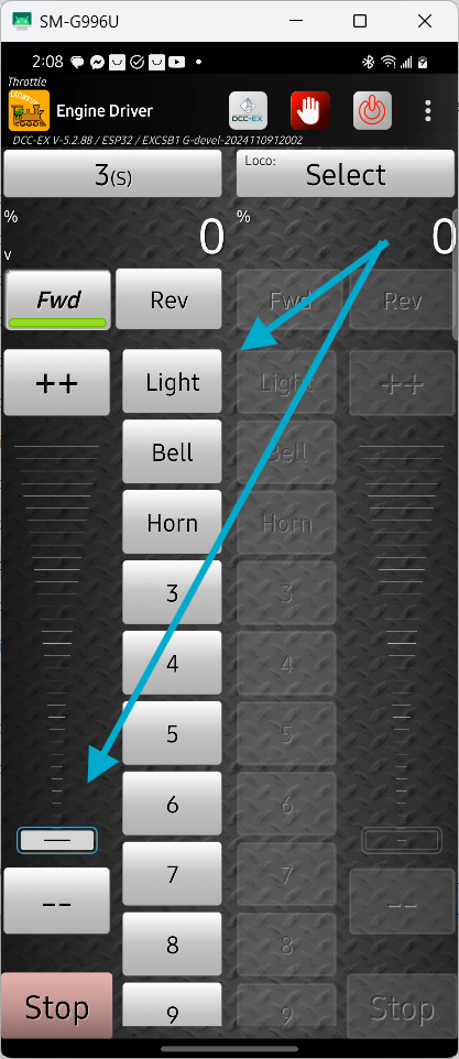
Fig 254: Operate Controls to Run trains
Additional information
Confirm startup
Fig 255: EX-CSB1 Startup - OLED screen
At startup of the EX‑CommandStation / Booster One Express the OLED screen shows useful information.
Line |
key |
Meaning |
|---|---|---|
1 |
DCC-EX |
EX-CommandStation version number |
2 |
Lic |
The licence under which the EX-CommandStation code is published |
3 |
Power |
Power State. ON / OFF / JOIN / etc. |
4 |
Free RAM |
Available RAM |
5 |
Wifi: |
The SSID / Network name |
6 |
PASS: |
The password for the Network |
7 |
IP: |
The IP Address of the WiThrottle / Native server |
Adding an EX-8874 Motor Shield
You can add an EX‑MotorShield8874 to the EX‑CommandStation / Booster One Express to increase the number of outputs from 2 to 4.
Note that the EX‑Installer does not have a simple way to configure the additional outputs so you will need to use the TrackManager feature to configure the outputs as needed in myAutomation.h in the Advanced Configuration page of EX‑Installer.
For example, to always set outputs C and D to be the second and third DCC MAIN outputs, you would create a AUTOSTART sequence that sets both outputs C and D to DCC MAIN mode in myAutomation.h.
AUTOSTART
   SET_TRACK(A,MAIN)
   SET_TRACK(B,PROG)
   SET_TRACK(C,MAIN)
   SET_TRACK(D,MAIN)
   POWEROFF
DONE
DCC Operation
The EX‑CommandStation / Booster One Express is set to operate in DCC mode by default. If you want to switch to any of the outputs to DC mode, you can find instructions on how to do that on the TrackManager page.
Booster Mode
The EX‑CommandStation / Booster One Express as the name implies can operate as a Command Station or a Booster. See EX-CS as a booster page for instructions on how to use the EX-CSB1 as a booster.
Full EX-CSB1 Operating Manual
EX-CSB1 Operating Manual
design files 
Next Steps
If you are happy with the default configuration of your EX‑CommandStation / Booster One Express there is nothing more you need to do.
If you want to change the way the WiFi is configured, just click next or go the WiFi Configuration page.
If you want to look at some other options to use as a controller (throttle) then have a look at the Choosing a Throttle (Controller) page.
If you want to add a roster, turnout/points, routes or automations look at the EXRAIL Automation & Animation page.