![]()
Semaphore or servo signals


Important considerations for servo operation
Test, test, test your servo parameters prior to connecting to an actual semaphore arm. If you have defined angles that exceed the physical limits of your signal, you will likely damage it and/or the servo mechanism.
Treat each servo and signal as an individual as not all servos (or signals for that matter) are created equal. An angle that works with one servo and associated signal will not necessarily provide the exact same result with another. Differences in servo brands, mounting methods, and even normal manufacturing tolerances will need to be factored in to the servo angles in use.
Use flexible wire to connect your servo arm to the signal. Using a flexible connection between the signal and the servo mechanism means if anything does go wrong such as the signal getting jammed or an incorrect servo angle being sent, it reduces the chance of damaging the signal or servo.
Defining semaphore or servo signal objects
To define semaphore signal objects, this is accomplished by using the servo signal command available in EXRAIL.
Note that unlike turnouts or points, there is no equivalent command available in the serial console to define signals.
The command available is:
SERVO_SIGNAL(vpin, red_position, amber_position, green_position)
It’s imperative to get the correct servo positions defined for the aspects in use to ensure that not only does the semaphore arm move to the correct position, but that it doesn’t move the arm beyond the physical limitations of the mechanism which could cause damage.
To do this, you can use the <D SERVO vpin position profile> command via the serial console of your EX‑CommandStation, which will move the servo arm to the defined position, using the specified profile.
It is recommended to test all positions required for the aspects to ensure the signal operates as desired, and to perform these tests before physically connecting the servo to the signal. When specifying a profile, use profile 4 for “Bounce”, which is what is used by the SERVO_SIGNAL(...) command and will give you an accurate indication of the servo movement for each tested position. For example, a suitable test command might be <D SERVO 100 400 4> to test the servo connected to the first row of headers on the PCA9685 module, using the “Bounce” profile.
For more information on servo modules and servos, refer to the information on the Connecting a Servo Module page.
What if I don’t have three aspect signals?
If you only have two aspect signals, you specify “0” for the unused aspect.
For example, SERVO_SIGNAL(100, 100, 0, 400) will operate only the red or green aspects, SERVO_SIGNAL(100, 100, 250, 0) will operate only the red or amber aspects, and SERVO_SIGNAL(100, 0, 250, 400) will operate only the amber and green aspects.
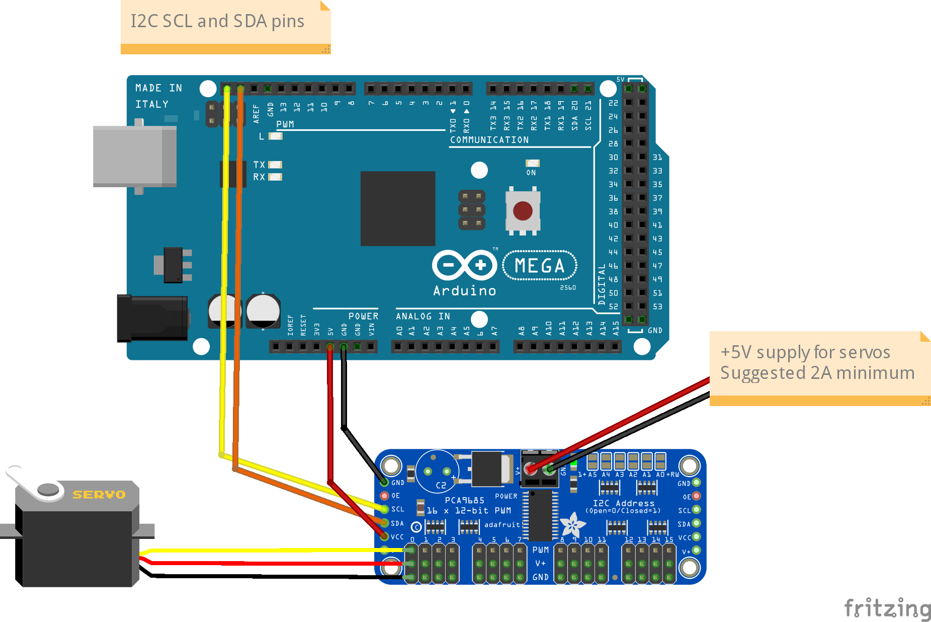
Connecting the signals
You will need to connect your servos to a PCA9685 servo module, with the module connected to the I2C interface of your EX‑CommandStation as per the following diagram:
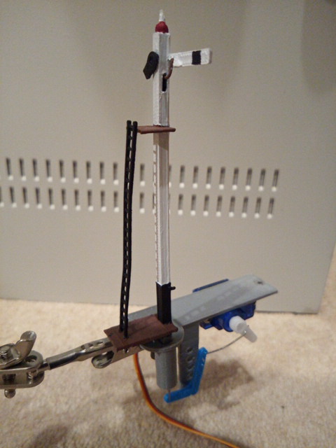
While the focus of this section is on the electronic connections and software control of the signals, the following diagram outlines an example of connecting the servo to the semaphore signal arm using flexible piano wire.
For more information on servo modules and servos, refer to the information on the Connecting a Servo Module page.
Controlling semaphore or servo signals
Controlling semaphore/servo signals is exactly the same as light signals, skip to Controlling signals for information on controlling signals.