Open the Play Store app on your phone or tablet and search for “EX-Toolbox”.
Once installed, open EX‑Toolbox and it will go through the initial setup wizard where it will ask for one permission, and for which which theme you would like to use.
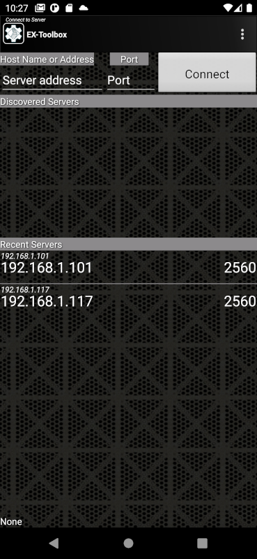
After you complete the setup wizard, you will be shown the ‘Connection’ Screen.
This is the most common way to connect. If the server you want to connect to is in the list, simply click on it and you will be taken to the ‘CV-Programming’ screen.
If the server does not appear in the recent list try one of the other two methods. Your server not appearing in the recent list is not necessarily a problem and there can be a number of reasons why.
So… just because a server is in this list, doesn’t mean that EX‑Toolbox will be able to connect to it.
Direct USB
As of Version 0.1.35 of EX‑Toolbox, the discovered server list will also include an entry ‘DCC-EX-USB-OTG’ if you have a EX‑CommandStation connected directly to your phone or tablet using a USB on-the-go (OTG) cable.
Note
The direct USB connection is only supported on Android devices that support USB on-the-go (OTG).
In general USB-C to the USB-C cables are automatically OTG, but if you are using a USB-C to USB-A cable, you will need to check that the cable supports OTG. If it doesn’t, the ‘DCC-EX-USB-OTG’ entry won’t appear in the discovered server list.
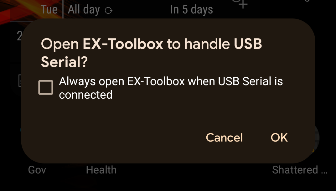
Anytime you connect any USB device to your phone or tablet, you will likely get a pop up asking if you want to allow EX‑Toolbox to access the USB. IF you connect devices other that an EX‑CommandStation to your phone or tablet, just cancel the pop up, but if you only connect an EX‑CommandStation you can check the box to always open EX‑Toolbox.
If the server you want to connect to is in the list, simply click on it and you will be taken to the ‘CV-Programming’ screen.
A server being in this list does not necessarily mean that you will be able to connect it now. It just means that you have successfully connected to it in the past.
Type in the IP address and Port of the EX‑CommandStation and press Connect.
To find your EX-CommandStation’s IP address and Port refer you original setup or, if you have a OLED screen on your command station the details will be displayed on it.
If you only ever connect to one EX‑CommandStation you can effectively bypass this screen by setting the ‘Auto-Connect to WiThrottle Server?’ preference.
on the main line (MAIN) - Operation mode / Ops Mode
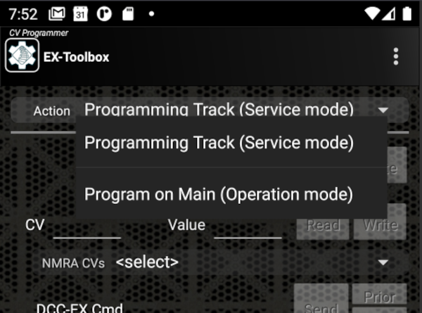
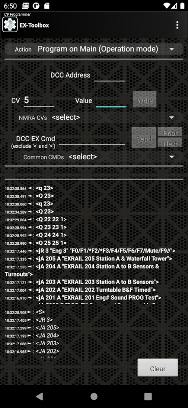
By default EX‑Toolbox shows the Service Mode options. To switch to Operation Mode, select “Program on Main (Operation Mode)” on the drop down list at the top of the screen.
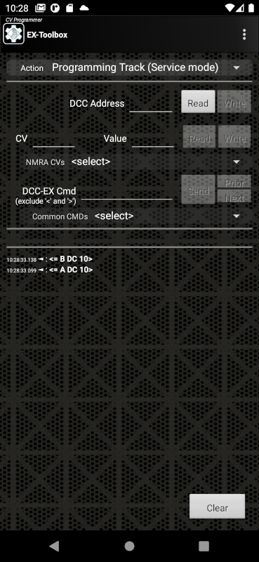
Service Mode CV Programming is available form the ‘CV Programming’ screen, when ‘Programming Track (ServiceMode)’ is selected in the drop down list at the top of the screen.
Service Mode CV Programming allows you to both Read (if the decoder/loco supports it) and Write CVs.
You do not need to know the DCC Address of the decoder being changed, as all decoders/locos currently on the programming track will have the CV changed at the same time.
Operation Mode CV Programming is available from the ‘CV Programming’ screen, when ‘Program on Main (Operation Mode)’ is selected in the drop down list at the top of the screen.
Operation Mode CV Programming ONLY allows you to Write CVs.
To use Operation Mode CV Programming you must know the DCC Address of the decoder/loco you want to change. Note: you should never try to change the DCC Address of the decoder/loco using Operation Mode CV Programming.
To write a CV value to the decoder, enter the DCC Address of the decoder, enter the CV number, enter the value and click the Write button on the CV row.
If you select a ‘common CV value’ it will enter the CV number into the field. From there follow the instructions above for writing the CV.
Assumes that you have already configured the ‘Master’ to be the way you want it and the other locos to behave.
The ‘Master’ should be the naturally slowest loco of the set, not necessarily the one that will be run in the lead position. i.e. Test your locos on their default settings first, and find the slowest.
The low speed test uses a speed setting of 5 (0-126). If your locos don’t start moving at that setting it would be advisable to adjust Low speed setting and/or the Kick Start of the ‘Master’ first.
Assumes that, at least, the ‘Second’ loco is configured to use the High, Mid, Low CVs, not the full 28 step ‘Speed Table’. (Part of CV29) Not critical, but it is advisable to have the ‘Master’ also use the High, Mid, Low CVs.
The CV Programming Page of EX‑Toolbox has a feature specific to CV29. When you read CV29, it explains what you need to change the value to to disable the ‘Speed Table’.
It is highly advisable that BACK-EMF is turned off on all locos that will be run in a consist. If you don’t you will likely encounter surging of the locos as they speed up and slow down under individual load.
BACK-EMF is referred to by some manufacturers as ‘Dynamic Compensation for Speed Stabilisation’, ‘Scaleable Speed Stabilisation’ or ‘Load Compensation’. Unfortunately there is no standard way to disable BACK-EMF. You will need to refer to the manuals for your decoders.
This page has a detailed explanation of BACK-EMF and details on how to change it for a number of manufacturers.
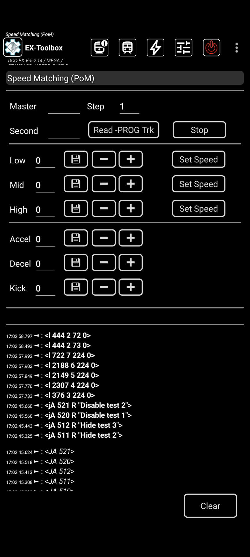
Open EX‑Toolbox and go to the Speed Matching screen.
Put the/a second (non-master) loco on the PROG track. (see Notes)
Click Read -PROG trk.
This reads 8 CV values, including the loco address and CV29, and loads them in to the fields, with a 3 second delay between each read. Watch for any -1 responses (failed reads), and redo the read if any have failed.
Put the ‘Master’ on the MAIN track (the loop of track), along with the ‘Second’ loco.
Enter the DCC address of the Master.
Click the Low Set Speed button.
Watch and adjust the speeds of the Second loco in relation the Master, util they run at the same speed:
If the ‘Second’ is too slow, either:
Edit and increase the Low value and click Write.
Click the + button.
If the ‘Second’ is too fast, either:
Edit and decrease the Low value and click Write.
Click the - button.
Repeat for the ‘Mid’ Speed.
Repeat for the ‘High’ Speed.
Adjust the decoder momentum (Acceleration/Deceleration) and Kick Start as needed. Test by starting and stopping the locos from the three different speeds.
If you have more locos to match, repeat from step 2.
By default, the + and - buttons change the CV values by 1. You can change this step amount by editing the ‘Step’ field. e.g. When I start on a loco, I normally have the Step at 10. When it gets closer to a match I change the step to 1.
You don’t need a separate PROG track. You can use the ‘Track Manager’ screen to temporarily set the loop of track to PROG for steps 2-3, then change it back to MAIN for steps 4 on.
Some decoders don’t support Kick Start.
Some decoders don’t allow you to turn BACK-EMF off. Check your decoder manual.
The low speed test uses a speed setting of 5 (0-126). If your locos don’t start moving at that setting it would be advisable to adjust Low speed setting and/or the Kick Start of the ‘Master’ first.
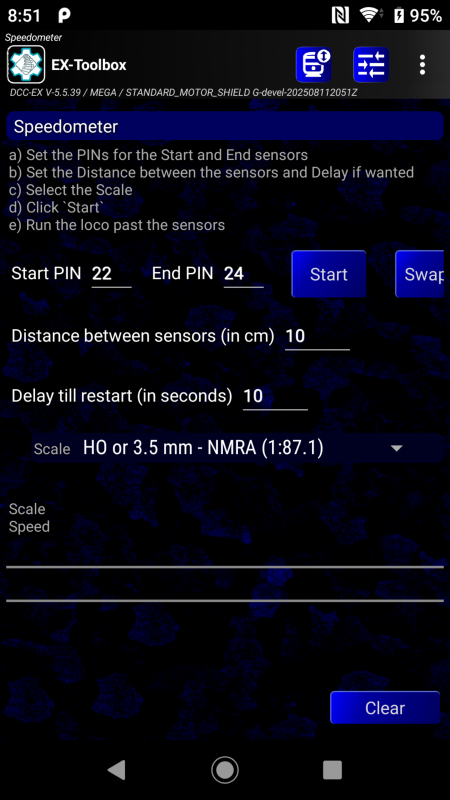
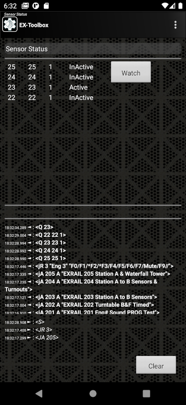
The Speedometer allows you to calulate the scale speed of a loco as it passes two defined sensors. The sensors can be of any type, but must be configured in your EX‑CommandStation and be a known (any) distance apart.
Define you sensors in the EX‑CommandStation configuration, and note their numbers.
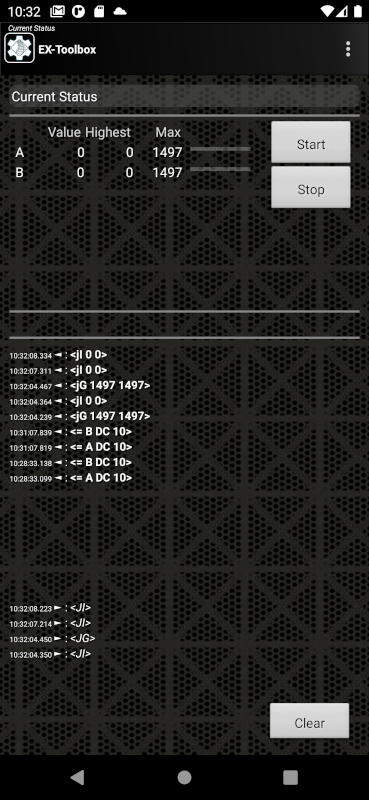
Enter the distance between the sensors, and select the Scale.
Put the loco you want to measure on the track before the first sensor.
Start the loco moving.
The Speedometer will display the speed as the loco after it passes the second sensor.
The speed and times will automatically reset after 10 seconds, but you can overide this by clicking the Start button. Or you can change the delay period.
To check the speed in the opposite direction, simply reverse the sensor numbers, using the Swap button.
The Speedometer will remember the last used sensors and distance between sessions.
Example configuration of two IR sensors in mySetup.h
SETUP("<S 22 22 1>");// Infrared Or Optical Sensor {S22} on pin 22SETUP("<S 23 23 1>");// Infrared Or Optical Sensor {S23} on pin 23
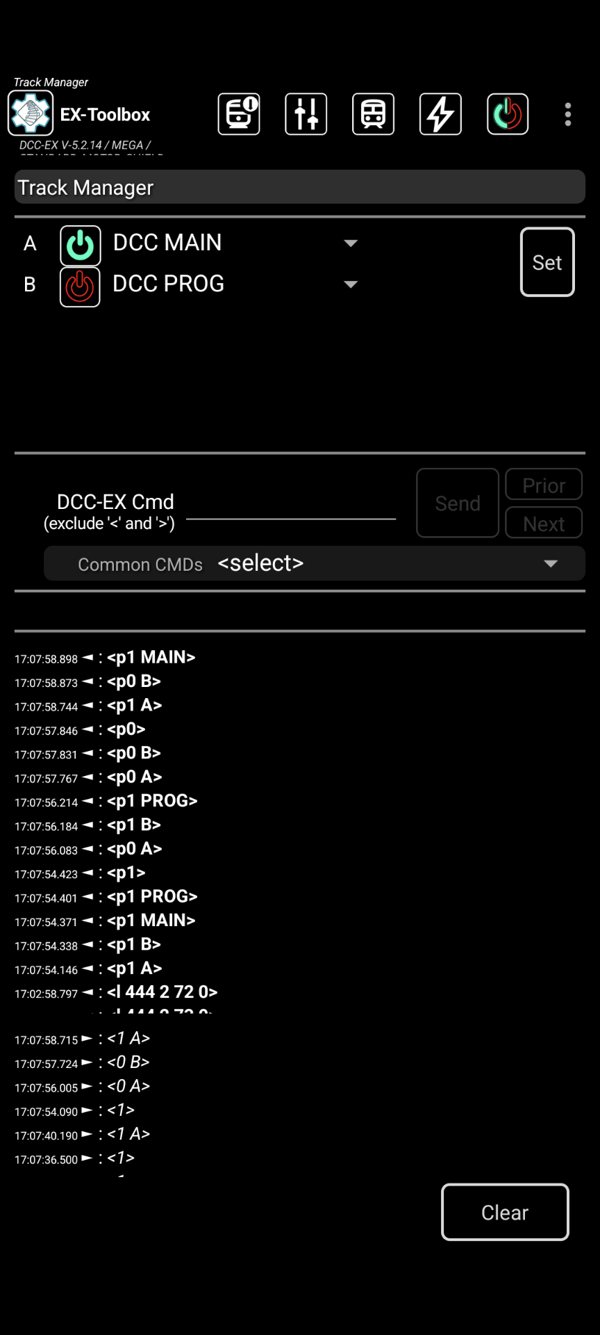
Track Manager allow you to change up to 8 channels (depending on the Motor Driver you are using)
Each channel can be one of:
DCCPROG - Programming Track
DCCMAIN - Main Track
DC
DCreversedpolarity(DCX)
OFF
Select the value you want for the channels and click Set
Note. If you select DC or DCX you must select a DCC address for the channel before pressing Set. What ever address you select, selecting that address on your throttle (e.g. Engine Driver) will result in the DC locomotive on the track connected to that channel to respond.
Note. Only one channel can be PROG. If you select more that one, one will turned OFF.
The servo motor test screen will allow you to test and fine tune the settings needed for configuring servo motors attached to the EX‑CommandStation. This is intended to be temporary. To permanently configure a servo motor you will need to record the values and include the in the configuration of your EX‑CommandStation.
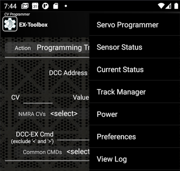
To access the Servo configuration screen either:
Swipe Right from the Sensor Screen
Swipe Left from the CV Programming Screen
Select ‘Servos’ from the Menu
On the Servo motor screen,
Enter the VPin of the servo motor you want adjustment
Enter any known starting values for Close, Mid, Throw
Test the Close, Mid, Throw positions by pressing the appropriate button. The servo will move to that position.
Fine adjust any of the three positions by using the + or - buttons The servo will gradually move.
when you are happy, record the three values
EX‑Toolbox remembers the servos that you have changed (up to 10) in this and previous sessions, and you can select one of the previous servos from the drop down list. EX‑Toolbox will restore the last settings you used for the selected servo to the main fields.
(The WiFi Settings screen is only available when connected to EX-CommandStation version 5.7.0 and above.)
Prior to version 5.7.0, WiFi configuration for EX‑CommandStation was done through options in the config.h file. This method required users to modify the firmware (by editing config.h) and recompile it for their specific WiFi settings.
From version 5.7.0, it is necessary to use a new WiFi configuration method, which involves connecting to the EX‑CommandStationafter you have flashed the firmware. You do so by connecting to the EX‑CommandStation via USB or by connecting to the WiFi Access Point network of the CS and issuing a set of new commands.
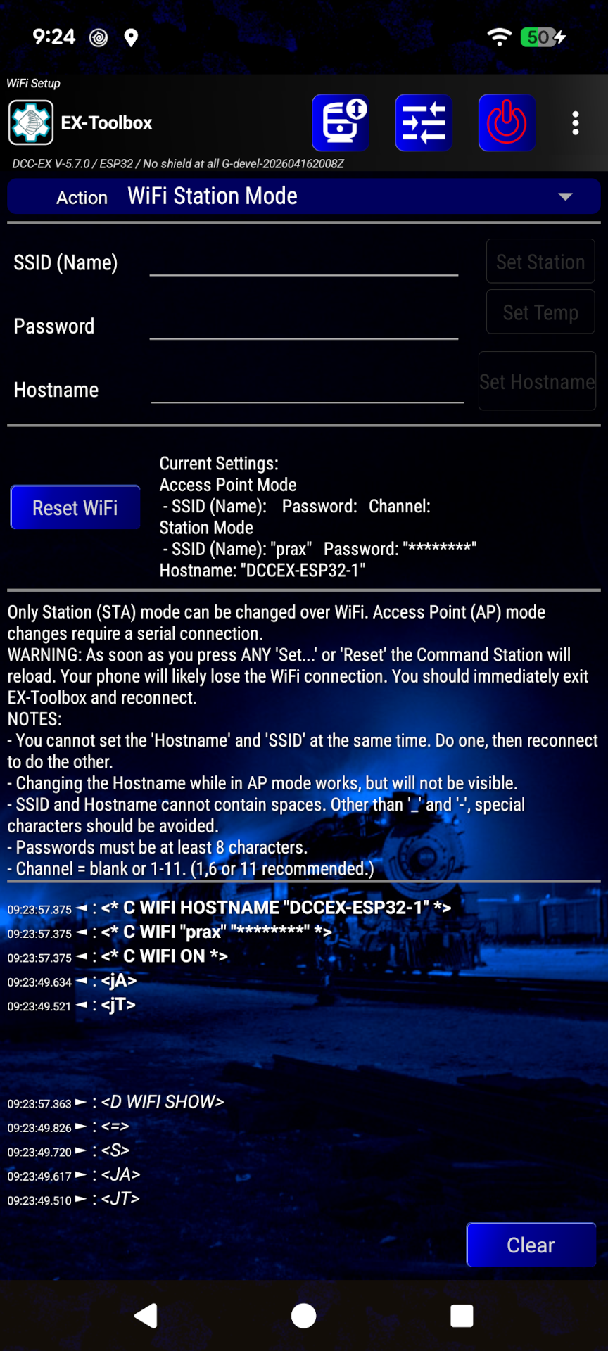
Station Mode WiFi configuration is available from the ‘WiFi Setup’ screen, when ‘WiFi Station Mode’ is selected in the drop down list at the top of the screen.
The Station Mode WiFi configuration allows you to set the SSID and password of the WiFi network that your EX‑CommandStation will connect to, and also allows you to set the hostname of the EX‑CommandStation on that network.
To change the Station Mode enter a SSID (the name of the network), and a password of at least 8 characters and presse either the Set Station button for a permanent change, or the Set Temp button for a temporary change.
To change the hostname enter the hostname and press the Set Hostname button.
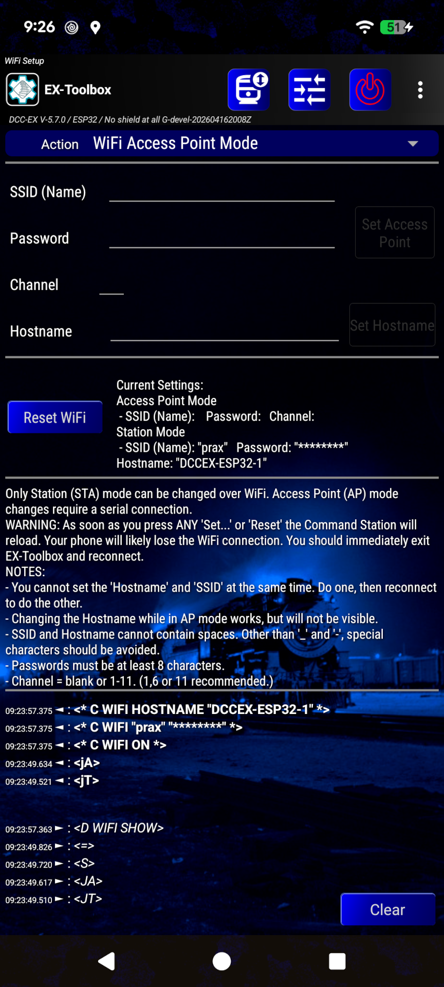
Fig 365: EX-Toolbox WiFi Settings Screen - AP Mode
Access Point Mode WiFi configuration is available from the ‘WiFi Setup’ screen, when ‘WiFi Access Point Mode’ is selected in the drop down list at the top of the screen.
The Access Point Mode WiFi configuration allows you to set the SSID, password and optional Channel of the WiFi Access Point network that your EX‑CommandStation will create, and also allows you to set the hostname of the EX‑CommandStation on that network.
Note
The ‘Access Point’ mode buttons will not become avaliable if you are connected to the EX‑CommandStation via WiFi, as you can’t change the Access Point mode settings over WiFi. You need to be connected via USB to change the Access Point mode settings.
To change the Access Point enter a SSID (the name of the network), and a Password of at least 8 characters and press the Set Access Point button.
To change the hostname enter the hostname and press the Set Hostname button.
Note
In every case above where you press one of the buttons, the Command Station will restart to apply the new settings. You will need to reconnect to the Command Station.
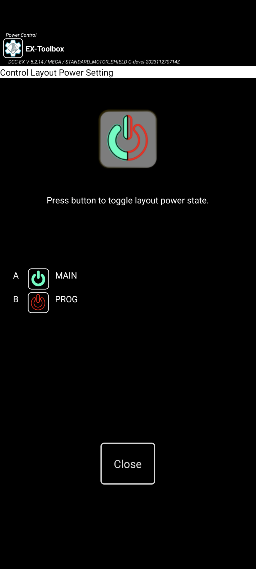
There are two ways to turn the Track Power on/off:
Power Screen - accessed from the menu
Power Action Bar button - needs to be enable in the preferences
The Power Screen can be accessed from the Menu ‣ Power. This will open the Power Screen where there is a simple button that to turn the power on or off. Use the Close button or Android’s Back button to return to the CV-Programming Screen.
If the Power Action Bar button is enabled, simply click on it to turn track power on or off.
Note
You can also optionally enable the Power Button on the Action bar in the preferences.
Accessed from any of the main screens via Menu ‣ View Log.
This screen allows you to view the internal EX-Toolbox log of events. (referend to as ‘logcat’).
The option to Start recording to file creates a user-accessible file that can be sent to the EX‑Toolbox app developers to assist you in resolving a problem.
The file will be located on your Android device/phone at:
Internal storage /Android/data/dcc_ex.ex_toolbox/files and will be named something like: logcat9999999999999.txt
Optionally enable the preference to include the timestamp on each line of the log.
EX‑Toolbox can’t normally connect to a EX‑CommandStation through JMRI, however it is possible if you LoadDCC++overTCPServer in the ‘DCC-EX’ menu in JMRI, then connect EX‑Toolbox to the additional server that is presented in Connection screen. It will be the same name as your JMRI Railroad name, but will have “ [DCC-EX]” appended to it.
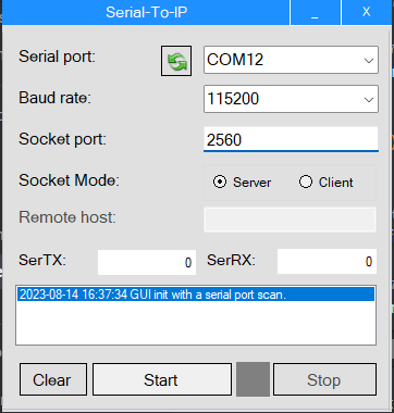
EX‑Toolbox can’t normally connect to an EX‑CommandStation via USB, however it is possible to temporarily create a USB to IP connection on your PC using tools like socat or SerialToIPGUI (for windows).
Note: Change S11 to the appropriate USB port. Whatever ‘COM’ number appears in the Device Manager, subtract 1.
i.e. ‘COM12’ in the Windows Device Manager becomes ‘/dev/ttyS11’
Using SerialToIPGUI (For Microsoft Windows) (Recommended):
Enter the IP address of your PC (The one running socat or SerialToIPGUI)
Enter the port of ‘2560’
Click connect
Important
This ‘trick’ only supports a single connection at a time. So it is important that JMRI (if you are using it), or the Arduino IDE Serial Monitor, or anything else that might be using the COM (USB) port are shut down first.