Makerfabs ESP8266 - Update AT Version with an Arduino Mega
Unfortunately many of the Espressif ESP8266 based WiFi Boards that are available for sale routinely come with versions of the firmware that simply do not work with EX‑CommandStation. The only boards guaranteed to work out of the box are the ones designed in a partnership between DCC-EX and Makerfabs. The board are the EX-WifiShield 8266 available through our reseller network, and the Makerfabs ESP8266 WiFi Shield. If you have a Makerfabs shield that was made between May 2023 and October 2023, your board may have faulty firmware.
Warning
The instructions on this page have been proven to work on Linux PCs, so will probably work on macOS PCs (Apple), however attempts to get them to work on Microsoft Windows PCshave so far been unsuccessful.
Out of the box, the small run of MakerFabs ESP8266 shields made in late 2023 mentioned above shipped with a broken firmware on the chips from the Expressif factory that Makerfabs use in their production. This version is unstable when used with DCC-EX as well as other applications. To flash version 1.7.4 onto the board follow these instructions. Do NOT use these instructions to update any EX-WiFiShield 8266 boards since they do not need updating. Known good boards have the DCC-EX logo on the bottom and are stamped with v1.1 or later. The joint DCC-EX/Makerfabs board have a much easier process to update them should they ever need new firmware in the future.
The esptool can be download separately, but the easiest way to get it is to use our EX‑Installer which will automatically download it if you select the appropriate options.
Find the folder in which the EX-Installer-Win64.exe or EX-Installer-Win32.exe was saved. Generally this will default to downloading to the downloads folder but your browser may be configured differently.
3.2. Put the Makerfabs ESP8266 WiFi shield on the Arduino Mega (if it is not already)
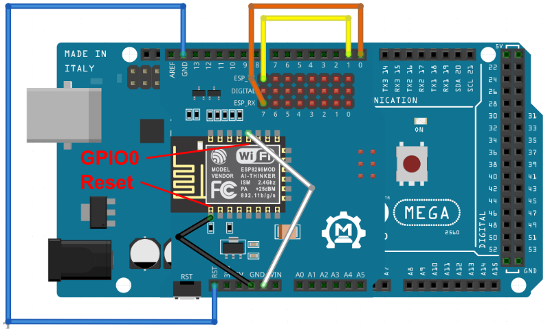
3.3 Connect the jumpers so that:
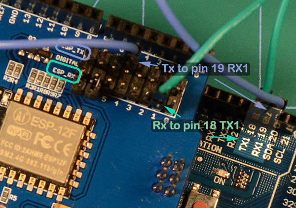
the RX of the ESP8266 is connected to the RX/D0 of the Arduino, and
the TX of the ESP8266 is connected to the TX/D1 of the Arduino
3.4 Connect the RST (Reset) of the Arduino to GND on the Arduino
3.5 Prepare two jumper wires to GND (loose ends)
Stacked Mega and Wifi Shield - Jumpers. Note: White and Black wires will be loose are this point
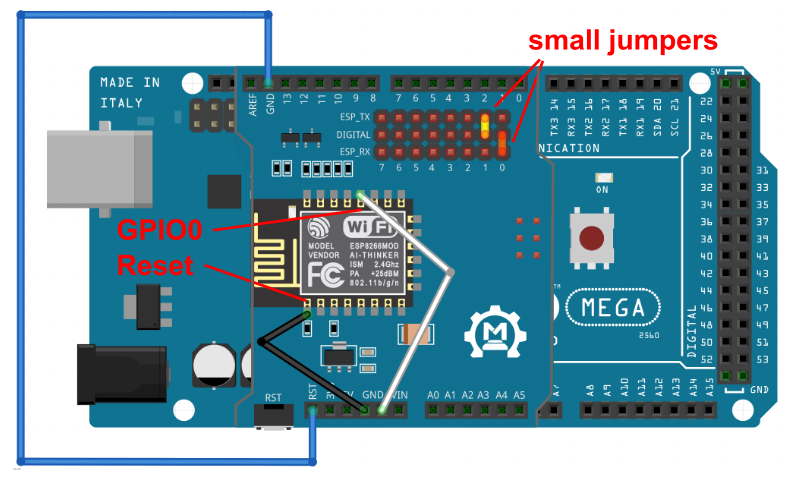
Alternate
Stacked Mega and Wifi Shield - Using the small, simple jumpers/plugs that came with the shield. Note: the White and Black wires will be loose are this point
Make sure the Installer has been closed before continuing.
5.1 open a command prompt
For Windows
click Start Menu
Type cmd and press the Enter key
Go to the folder you downloaded the ESP8266_1MB_AT1_7.bin file to (normally ‘Downloads’) by entering:
c:Enter cd\user\<username>\downloadsEnter (Replace <username> with your username on the PC)
For Apple macOS
Click the Launchpad icon in the Dock, type Terminal in the search field, then click Terminal or In the Finder , open the /Applications/Utilities folder, then double-click Terminal.
Go to the folder you downloaded the ESP8266_1MB_AT1_7.bin file to by entering:
cd~\DownloadsEnter
For Linux
On Ubuntu, you can hit ctrl+alt+T together to open a terminal. Or right-click anywhere on the desktop and select OpeninTerminal which will open the terminal with the desktop folder selected. Or press the Windows key and type terminal
Go to the folder you downloaded the ESP8266_1MB_AT1_7.bin file to by entering:
cd~\DownloadsEnter
5.2 Prepare the long command line. (but don’t press Enter yet)
For ESPTOOL and PORTNAME insert values from the steps above
For Example for Windows PCs : (if the Arduino is connected on COM3) C:\Users\<userName>\AppData\Local\Arduino15\packages\esp32\tools\esptool_py\4.5.1\esptool--baud38400--portCOM3write_flash--erase-all--flash_freq40m--flash_modedout--flash_size1MB0x0ESP8266_1MB_AT1_7.bin
Note: that <username> needs to be replaced with ‘your’ user name on the PC.
If the program is python (iOS or Linux) you need to prepend python3 like this: (If the Arduino is connect on /dev/ttyUSB0) python3~/.arduino15/packages/esp32/tools/esptool_py/4.5.1/esptool.py--baud38400--port/dev/ttyUSB0write_flash--erase-all--flash_freq40m--flash_modedout--flash_size1MB0x0ESP8266_1MB_AT1_7.bin
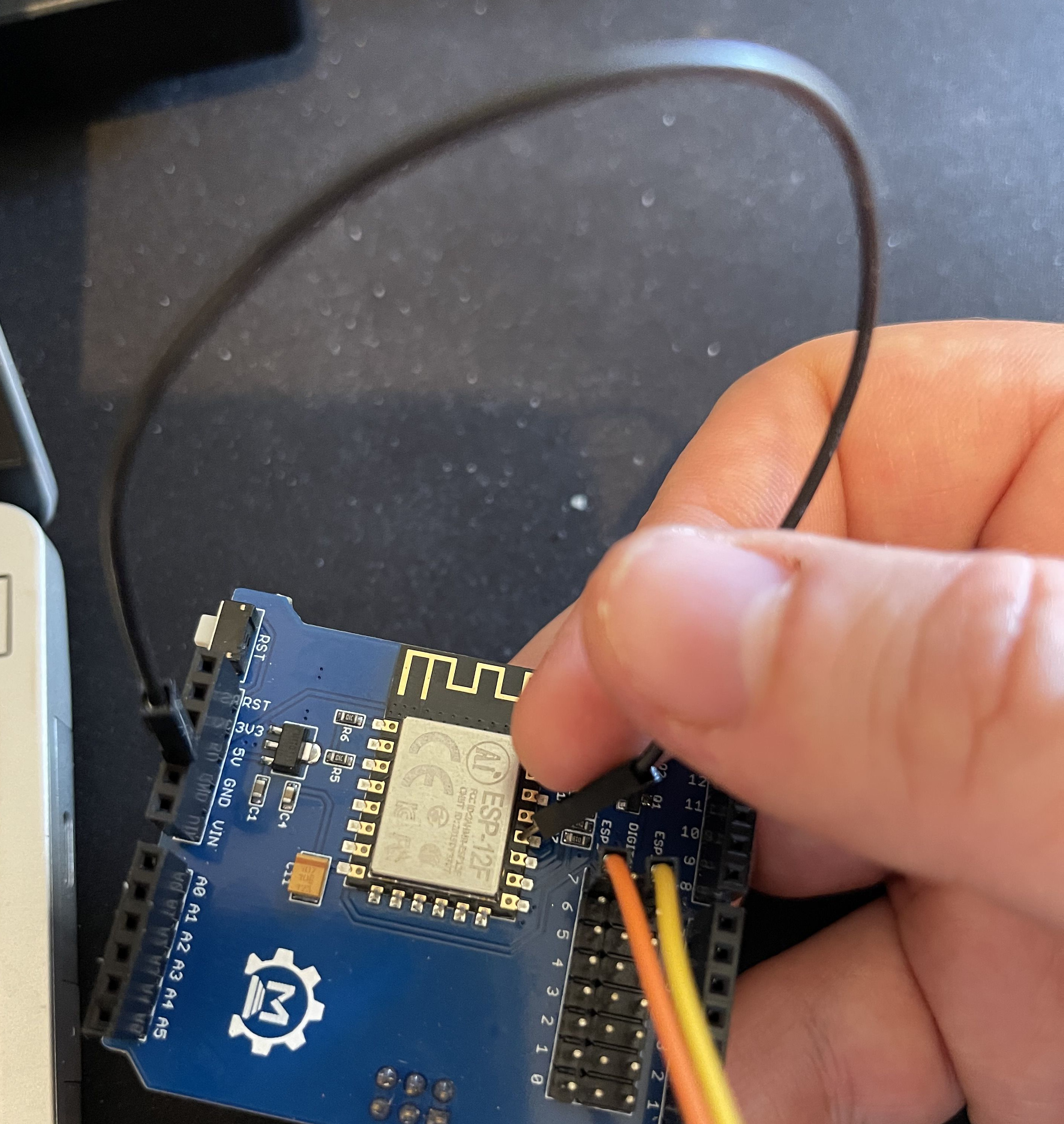
5.3 Locate the Reset and GPIO0 pads on the ESP8266.
The GPIO0 pad is the fourth pad from the bottom on the right, next to the “P” in “ESP-12F”.
The Reset pad is the top pad on the left, closest to the resister labelled “R6”.
5.4 Press enter on the above command line.
You should see connecting and dots and dashes.
5.5 Take one GND jumper and HOLD (keep holding) to GPIO0 pad
Note: The GPIO0 pin is the fourth pin from the bottom on the right, next to the “P” in “ESP-12F”. See picture below.
7.6 If you have not already done so, run the EX‑Installer and configure your EX‑CommandStation to use the WiFi shield. Note: this is not necessary if it was done before you started flashing the WiFi firmware. i.e. Flashing the firmware does not upset the software you loaded on the Arduino.
You should now be able to set your EX-CommandStation to use, and if all went well it should work.


 available through our reseller network, and the Makerfabs ESP8266 WiFi Shield