DCC & DC Technical Details
Before you begin
This is not your father’s DC railway which used DC transformers for Cab control.
Turn off, unplug the AC power cord, and disconnect your current DC transformer(s) / power supply(s) from the DC layout track to place in a box for safe keeping.
You will instead be using a regulated DC (Laptop) 12-18 Vdc 3-5Amp power supply to your Motor Shield and or Motor Board (booster) to run all your DCC Locos and analogue DC Cabs on all your individual tracks/districts/blocks.
You will be using DC (Pulse Width Modulation PWM) to drive the DC engines, Not DC Direct Current (-0 +16v).

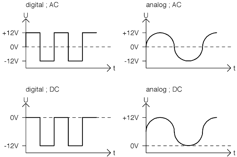
Waveform Comparison
Note
These modes, (PWM) vs analogue DC are totally incompatible with one another and if crossed will result in magic smoke and a burned out Motor Shield and or USB connector.
DCC(PWM) is detected on a multimeter as an AC signal but in a square wave form, not as a sine wave
DC(PWM) is detected on a multimeter as a DC signal in a square wave form, not as a direct current wave
The DC(PWM) track is Power supply dependent and needs a varying amount of 0 zero to maximum Vdc passed to the track of 12 or 16 or 18vdc, depending on whether they’re N, HO or G scale engines.
Note; The signal is detected as DC on this track, from 0Vdc to max +xxVdc depending on the Motor Shield DC power supply output. The DCC-EX 122.55Hz PWM DC motor signal allows for better functioning and better running than most competing systems.
TrackManager DCC(PWM) vs. DC(PWM) wave forms
A simplified representation of what the dual (PWM) signals might look like through the track:

DCC PWM signal
Note
Note on PWM frequency
Different microcontrollers utilise different PWM frequencies, and at present, these default frequencies are in use rather than using software to define them.
The side effect of these differing frequencies is that you may notice humming or sometimes squealing noises from older DC motors.
The known PWM frequencies are:
Mega2560 - 122.55Hz
ESP32 - 131Hz
STM32 Nucleo - typically 1000Hz
Additional Notes
This is not zero (0) stretching. We do not support the zero stretching address function, found on Digitrax and Lenz command Stations on purpose. The constant dual DCC electrical signal may damage certain types of older DC motors if left on for a long time.
So never put a DC locomotive on a DCC track.
Unlike Digitrax and Lenz 0 Zero stretching DCC (PWM) signal which leaves the engine lit up and humming loudly with the throttle and engine at 0 speed, because it is receiving a Dual DCC(PWM) aka AC signal, while the EX‑CommandStation TrackManager is dead quiet and at rest at 0 speed.
One key difference to note in comparing DCC vs. DC is that in DCC mode, forward/reverse is determined by the DCC decoder, not the track, whereas in DC mode the direction is dependent upon the track polarity.


